Shunting type sampling and emptying device for centrifugal pump

A centrifugal pump and shunt-type technology, which is applied in the direction of sampling devices, components of pumping devices for elastic fluids, pumps, etc., can solve the problems of inconvenient control of the flow rate, high requirements for physical strength and arm strength of operators, and reduce sampling Difficulty, accurate and convenient sampling, easy disassembly and operation

Pending Publication Date: 2019-10-18
大庆仁满源科技开发有限公司
View PDF0 Cites 0 Cited by
  • Summary
  • Abstract
  • Description
  • Claims
  • Application Information

AI Technical Summary

Problems solved by technology

[0003] The present invention aims to solve the problem that the existing sampling and venting device for centrifugal pumps is inconvenient to control the flow rate during the sampling process, and requires high physical strength and arm strength of the operator, and further provides a split-flow sampling and venting device for centrifugal pumps

Method used


Image

  • Shunting type sampling and emptying device for centrifugal pump
  • Shunting type sampling and emptying device for centrifugal pump
  • Shunting type sampling and emptying device for centrifugal pump

Examples


specific Embodiment approach 1

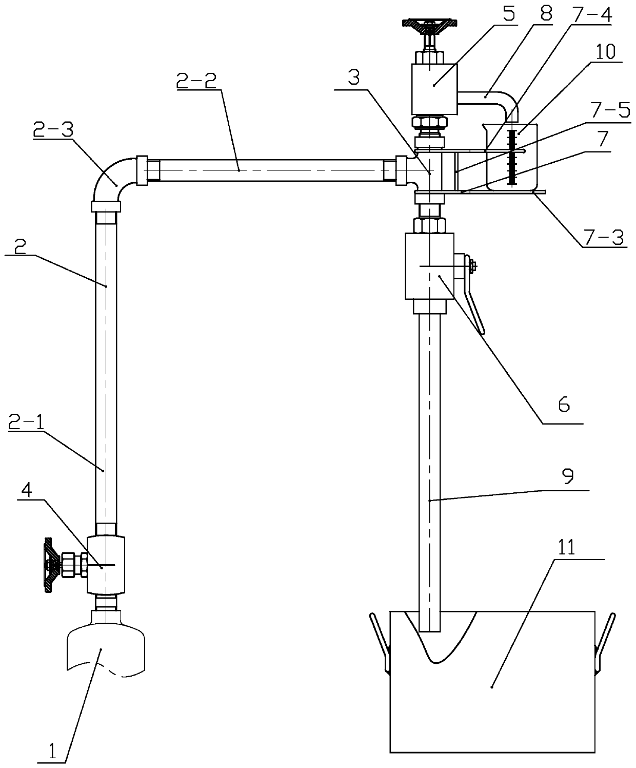
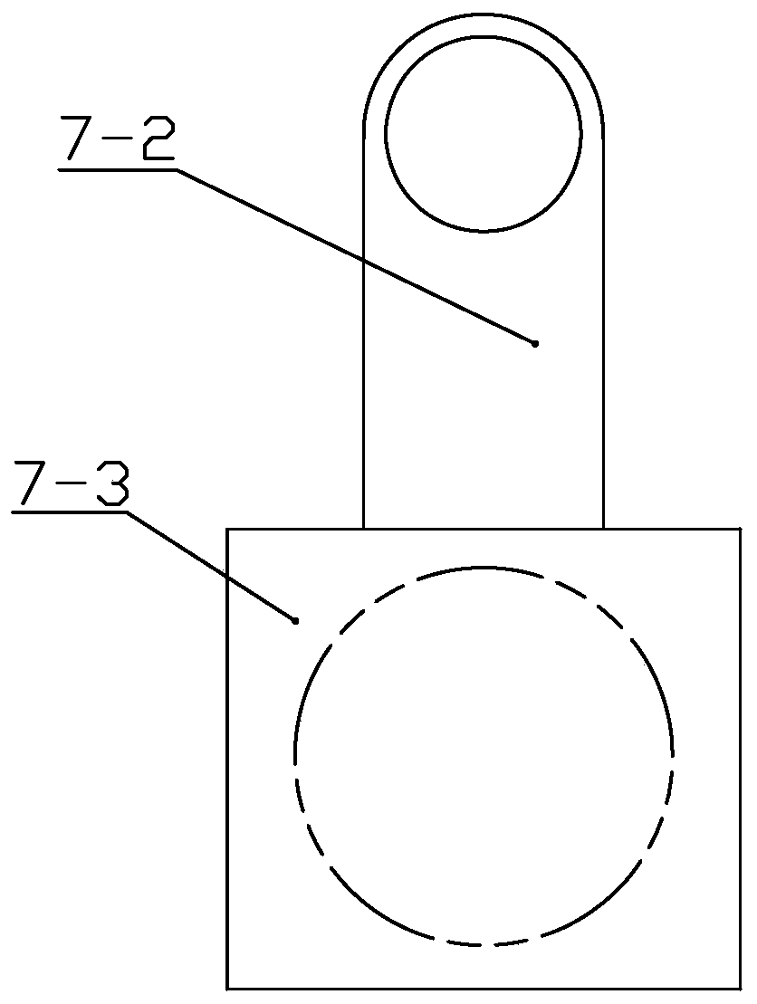
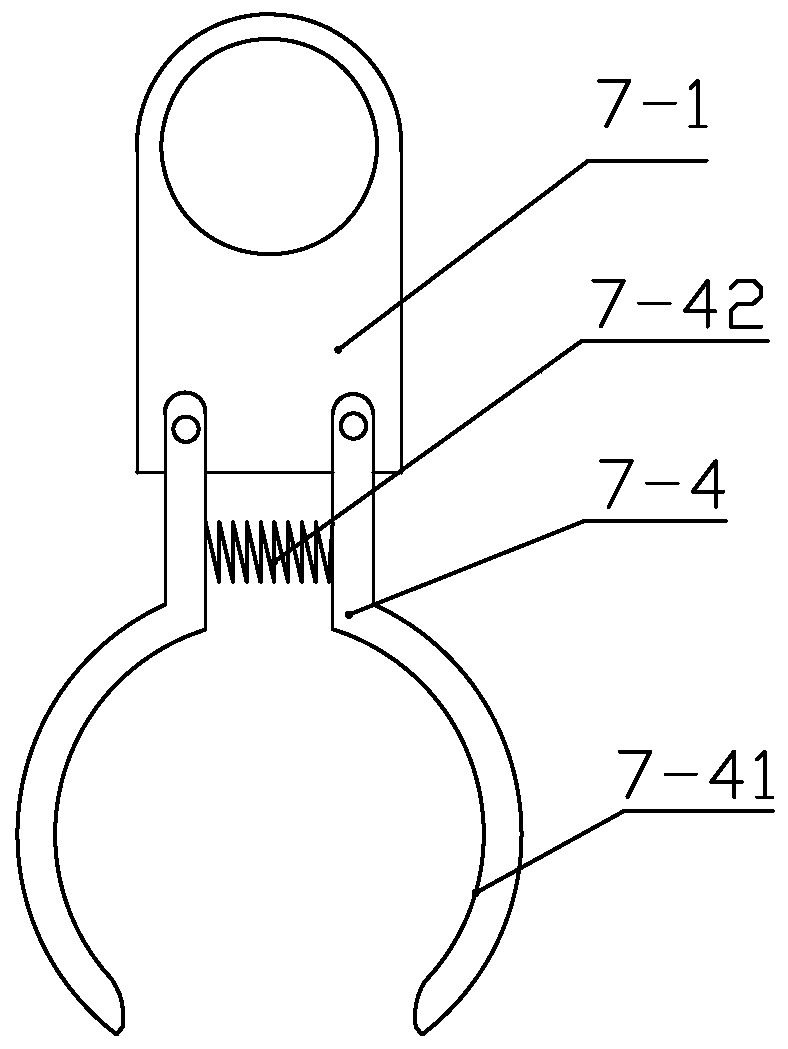
[0016] Embodiment 1: Combining Figures 1 to 3 Describe this embodiment, a centrifugal pump with a split-flow sampling and venting device, which includes a centrifugal pump 1, a main pipeline 2, a three-way 3, a stop valve 4, a sampling valve 5, a venting ball valve 6 and a measuring cup holder 7, and the main pipeline 2. One end is fixedly connected with the centrifugal pump 1, the other end of the main pipeline 2, the sampling valve 5 and the emptying ball valve 6 are communicated and arranged through the three-way 3, the shut-off valve 4 is arranged on the main pipeline 2, and the fluid outlet of the sampling valve 5 is connected to a solid. A sampling tube 8 is provided, a venting tube 9 is connected and fixed at the fluid outlet of the venting ball valve 6 , and the measuring cup holder 7 is fixedly arranged between the sampling valve 5 and the venting ball valve 6 . The main pipeline 2 is the top outlet pipeline of the centrifugal pump 1 . The venting ball valve 6 is a ...


PUM


Abstract

The invention relates to a shunting type sampling and emptying device for a centrifugal pump, and belongs to the technical field of oil field sampling equipment. The shunting type sampling and emptying device solves the problems that an existing sampling and emptying device for the centrifugal pump cannot conveniently control the flow rate in the sampling process, and the requirements for the physical strength and the arm strength of an operator are high. One end of a main pipeline is fixedly connected to the centrifugal pump, and the other end of the main pipeline, a sampling valve and an emptying ball valve communicate with each other through a tee joint, a shut-off valve is arranged on the main pipeline, a fluid outlet of the sampling valve is fixedly provided with a sampling pipe in acommunicating manner, an emptying pipe is fixedly arranged at a fluid outlet of the emptying ball valve in a communicating manner, and a measuring cup holder is fixedly arranged between the sampling valve and the emptying ball valve.

Description

technical field [0001] The invention relates to a split-flow sampling and venting device for a centrifugal pump, belonging to the technical field of oilfield sampling equipment. Background technique [0002] In the oilfield production process, it is often necessary to sample and analyze the transport fluid in the oil transport centrifugal pump, and to empty and discharge the gas and sludge brought by the fluid in the centrifugal pump cavity, so as to improve the pump calibration, so as to meet the requirements of the production process. The vent sampling device used in the prior art is to install a ball valve or a stop valve at the top outlet of the centrifugal pump, and the vent sampling is controlled by one valve. This structure has obvious defects: because the ball valve or the globe valve cannot control the flow well , and the sampling requirements are that the sampling outlet has a small flow rate and a stable flow rate to ensure accurate sampling. At the same time, the...

Claims


Application Information

Patent Timeline
Patent Type & Authority Applications(China)
IPC IPC(8): F04D15/00F04D29/00G01N1/10
CPCF04D15/0005F04D15/0088F04D29/007G01N1/10
Inventor 闫梓
Owner 大庆仁满源科技开发有限公司
Why Eureka
Try Eureka