
Manual lifting mechanism for fluid loading arm for ship on wharf

A lifting mechanism and marine technology, applied in the direction of clockwork mechanism, hoisting device, etc., can solve the problems of time-consuming and labor-intensive manual operation, accident-prone, heavy boom, etc., to prevent reversal and ensure safe operation

Inactive Publication Date: 2015-06-10
FOSHAN GAOFU PETROCHINA FUEL ASPHALT
View PDF4 Cites 3 Cited by
  • Summary
  • Abstract
  • Description
  • Claims
  • Application Information

AI Technical Summary

Problems solved by technology

[0006] At present, the boom is generally turned by hand, and the boom is placed horizontally for oil delivery or vertically stowed by releasing or tightening the wire rope. However, manual rotation of the handwheel is difficult due to the heavy boom Time-consuming and labor-intensive, and the staff are prone to misoperation, causing the handwheel to reverse and the boom to reset, which is prone to accidents

Method used


Image

  • Manual lifting mechanism for fluid loading arm for ship on wharf
  • Manual lifting mechanism for fluid loading arm for ship on wharf
  • Manual lifting mechanism for fluid loading arm for ship on wharf

Examples


Embodiment Construction

[0025] The preferred embodiments of the present invention will be described below with reference to the accompanying drawings. It should be understood that the preferred embodiments described here are only used to illustrate and explain the present invention, and are not used to limit the present invention.

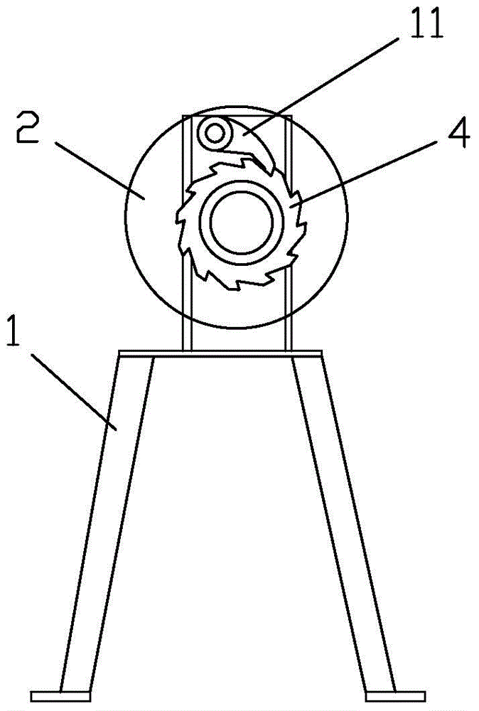
[0026] Such as Figure 1 to 3 As shown, the manual lifting mechanism of the fluid loading arm for the dock of the present invention includes a frame 1, the frame 1 is provided with a sheave 2 wound with a steel wire, the center of the sheave 2 is provided with a sheave shaft 3, and the sheave shaft 3 is fixed with The ratchet wheel 4, the frame 1 is provided with a pawl seat 5, the pawl 11 is arranged on the pawl seat 5, the sheave shaft 3 is fixedly connected to the driven shaft 6, the driven shaft 6 is provided with a first gear 7, and the pawl 11 can be inserted Inside the ratchet teeth of the ratchet wheel 4.

[0027] The first gear 7 and the second gear 8 are toothed, th...


PUM


Abstract

The invention discloses a manual lifting mechanism for a fluid loading arm for a ship on a wharf. The manual lifting mechanism comprises a rack, wherein a rope sheave wound with a steel wire rope is arranged on the rack, a rope sheave shaft is arranged in the center of the rope sheave and fixedly connected with a driven shaft, a ratchet wheel is further arranged on the rope sheave shaft, a first gear is arranged on the driven shaft, a pawl corresponding to the ratchet wheel is arranged on the rack, the first gear is connected with a second gear through teeth, the second gear is arranged on a driving shaft, and a hand wheel is fixedly connected to the tail end of the driving shaft. According to the manual lifting mechanism for the fluid loading arm for the ship on the wharf, the rope sheave rotates when the hand wheel is rotated, and the pawl is shifted on the ratchet wheel; when the hand wheel rotates reversely, the pawl enters teeth of the ratchet wheel, so that the rope sheave is prevented from rotating reversely, and safe operation is guaranteed.

Description

Technical field [0001] The invention relates to a ship body loading and unloading equipment on a wharf, in particular to a manual lifting mechanism for a fluid loading arm for a wharf ship. Background technique [0002] When loading and unloading oil or other liquid chemicals to ships at the wharf, an oil transfer arm is needed. [0003] At present, there are two main structural types of oil pipeline knuckle boom oil transfer boom cranes used in oil tankers and chemical tankers: [0004] A single-pipe or double-pipe oil pipeline is laid directly on or inside the boom of a hose crane, with elbows and flanges welded at both ends of the pipeline, and then directly connected to the hose; [0005] The other is to lay a single-pipe or double-pipe oil pipeline on or inside the crane boom, and install a rotating joint on the rotating root of the boom and the rotating shaft concentrically. [0006] In the prior art, the hand wheel is generally turned manually, and the steel wire rope is release...

Claims


Application Information

Patent Timeline
Patent Type & Authority Applications(China)
IPC IPC(8): B66D1/04B66D1/14
CPCB66D1/04B66D1/14
Inventor 阙伟坚陈文吉韦天养豆方杰
Owner FOSHAN GAOFU PETROCHINA FUEL ASPHALT
Learn More