
Instant log-on printer and its management method

A technology of printers and inkjet print heads, applied in typewriters, printing devices, printing, etc., can solve the problems of occupied rhythm, slow speed, large size, etc., and achieve the effect of clear printing effect, low operator requirements, and increased information volume.

Active Publication Date: 2016-02-24
HEBEI HUIJIN ELECTROMECHANICAL
View PDF6 Cites 0 Cited by
  • Summary
  • Abstract
  • Description
  • Claims
  • Application Information

AI Technical Summary

Problems solved by technology

[0004] At present, there are two types of all-in-one binding machines with printing function in the market. One is that the binding mechanism and the printing mechanism are arranged side by side, and the printing mechanism is set at the front end of the binding mechanism. When using, the information is pre-printed on the binding. Bring it on, and then enter the binding station. This design is huge in size. It only combines the printer and the binding machine together, which is twice the size of the ordinary automatic binding machine. It is pre-printed and cannot be printed in real time. Information The accuracy and timeliness are difficult to grasp, and effective traceability cannot be achieved; the other is the integrated design of the printing mechanism and the binding mechanism. The printing mechanism is fixed. 1. Spread the information and print it on the strap. Although this structure prints in real time and has a small size, it has relatively high requirements for the operator, because the operator must move in a straight line at a constant speed when picking up the banknotes by hand during the printing process, otherwise the printing effect will not be clear. It is difficult to control the manual operation to achieve uniform linear motion, and it needs to take up beats and slow speed

Method used


Image

  • Instant log-on printer and its management method
  • Instant log-on printer and its management method

Examples


Embodiment Construction

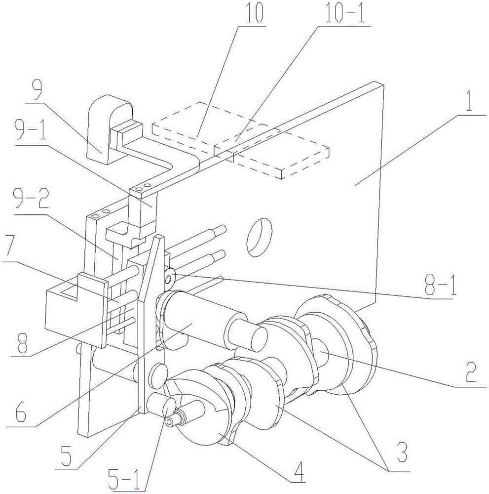
[0024] see figure 1 , the instant log-in type binding printer, the body structure includes a semi-embedded banknote handle positioning inlet channel and a strapping servo mechanism positioned on the frame 1 and arranged around the banknote handle inlet channel, the servo mechanism includes: belt conveying The camshaft 2 arranged between each assembly and the drive motor shaft, and the camshaft 2 are arranged on the camshaft 2 to form a sequence control pair The drive control cam 3 of each assembly and the intermediate drive mechanism connected to each drive control cam 3; the inkjet print head 9, control circuit and synchronous drive positioning mechanism are also arranged on the frame. The synchronous driving and positioning mechanism of the ink print head includes an end cam 4 positioned on the camshaft 2, a rocker 5 pressed against the end cam 4 by means of a pressure contact spring, and a slider 8 slidingly fitted with the other end of the rocker 5. The pair of rails 7, a...


PUM


Abstract

The invention discloses a real-time login type binding printer. A machine body structure comprises a half-embedded type money bundle positioning entrance channel and a binding trap servo mechanism positioned on a frame and encircled around the money bundle positioning entrance channel; similarly, an ink-jet printing head, a control circuit and a synchronous driving positioning mechanism are arranged on the frame. The key is that the synchronous driving positioning mechanism of the ink-jet printing head, comprises an end face cam positioned on a cam shaft, a rocking bar leaned and pressed on the end face cam by means of a contact spring, a gliding block slide rail pair in gliding fit with the other end of the rocking bar, and a supporting arm arranged on a gliding block and used for positioning the ink-jet printing head. The real-time login type binding printer integrally designs the printing and binding; the real-time login type binding printer is small in volume, simple in structure, quick in printing speed and needs not occupy additional tempo; the real-time login type binding printer prints in real time, and is good for tracing the source of the money bundle.

Description

technical field [0001] The invention belongs to the field of financial equipment, and relates to a banknote binding processing device, in particular to an instant login type binding printer and a control method thereof. Background technique [0002] With the rapid development of economic construction and the further reform and opening up of the financial industry, although the financial industry, large-scale commercial and banking institutions try their best to promote electronic transactions, bulk banknote transactions are still inevitable. The binding machine is an indispensable equipment for banks and other financial systems to complete the binding of banknotes. It is mainly used to bind small stacks of banknotes, such as 100 pieces, into bundles. [0003] In the circulation process of banknotes, in order to facilitate the traceability of problems, it is necessary to print information such as bank, operator, operating time, and location on the strap of each banknote, with...

Claims


Application Information

Patent Timeline
Patent Type & Authority Patents(China)
IPC IPC(8): B41J2/01B41J3/00B41J29/393
Inventor 孙景涛韩玉兰张振江郭杨杨陈芳萍张亚飞张红远魏江涛
Owner HEBEI HUIJIN ELECTROMECHANICAL
Learn More