
Mine power battery

A technology for power batteries and mines, which is applied in battery circuit devices, arrangement of multiple synchronous batteries, collectors, etc., can solve the problem of large application potential of lithium-ion power batteries, inconvenient installation, handling and disassembly, and increase in the volume of charging equipment and weight issues, to achieve the effect of light weight, light weight and weight reduction

Inactive Publication Date: 2015-06-03
NORTH CHINA INST OF SCI & TECH
View PDF4 Cites 20 Cited by
  • Summary
  • Abstract
  • Description
  • Claims
  • Application Information

AI Technical Summary

Problems solved by technology

[0005] 2. Lithium-ion power batteries have not been used in coal mine electromechanical power equipment so far, and the application potential of lithium-ion power batteries in coal mines is huge
[0016] This charging scheme is straightforward and simple in electric energy conversion, directly rectified from DC to AC, and at the same time, the addition of a transformer effectively realizes the electrical isolation of the input and output of the system. However, there are two shortcomings in this charging scheme. First, according to the structure of the transformer It can be seen from the principle that the addition of power frequency transformers increases the volume and weight of the entire charging equipment to a certain extent.
However, the addition of power frequency transformers in the main circuit and the addition of filter inductors on the DC side greatly increase the volume and weight of the equipment, making it difficult to install, transport and disassemble

Method used


Image

  • Mine power battery
  • Mine power battery
  • Mine power battery

Examples


Embodiment Construction

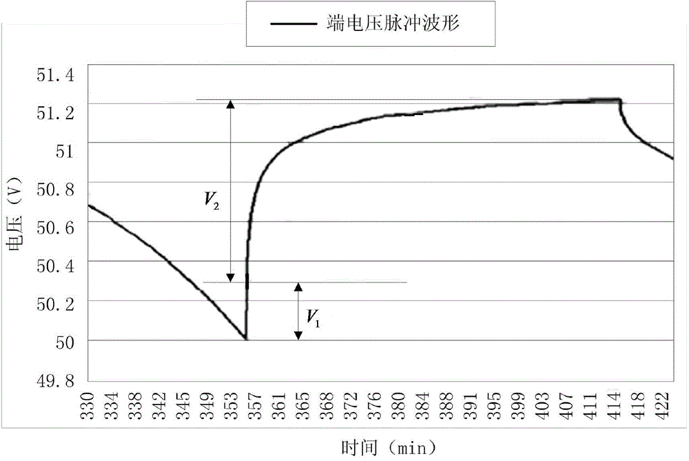
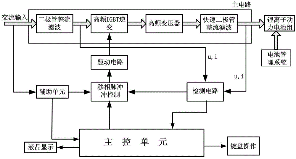
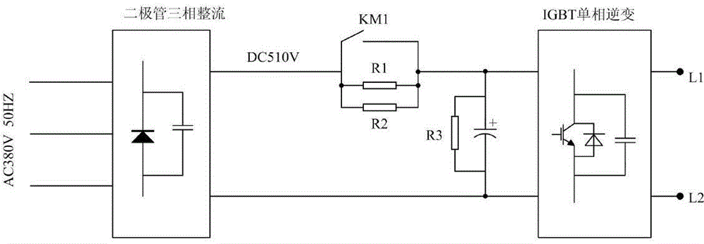
[0077] The block diagram of the overall design of the mining power battery disclosed by the present invention is as follows: figure 1 shown. The whole device is composed of charging main circuit, detection circuit, phase-shift pulse controller and main control unit based on single-chip microcomputer SPMC75F2413A, and adopts modular design mode. The main circuit is composed of a rectifier circuit (AC-DC) and a high-frequency direct current conversion circuit (DC-DC). The AC power passes through the AC contactor as the input voltage of the rectification module, and the rectified output DC voltage is used as the input voltage of the DC-DC converter. The control circuit is composed of SPMC75F2413A and auxiliary circuit. It sends out the charging control signal, detects the working state of the charger, realizes the man-machine interface, completes the detection and control of the output current and voltage, and realizes the control of the battery charging process.

[0078] 1. Re...


PUM


Abstract

The invention discloses a mine power battery, which comprises a charging main circuit, a detection circuit, a phase shifting pulse controller and a main control unit, wherein the detection circuit, the phase shifting pulse controller and the main control unit are respectively connected with the charging main circuit, the main control unit is based on a single chip microcomputer, the charging main circuit consists of a rectification circuit and a high-frequency direct current conversion circuit, and the main control unit detects a work state of a charger through the detection circuit, gives out charging control signals through the phase shifting pulse controller, completes the detection and the control on the output current and the voltage and realizes the control on the storage battery charging process. The mine power battery has the advantages that the safe and intelligent charging on a mine high-capacity lithium ion battery can be completed, the step for replacing the traditional mine lead-acid storage battery with the mine lithium ion battery can be promoted, the size is small, the weight is light, and the miniaturization and the light weight of the charger can be realized; under the condition of the same power, the size can be reduced to 1 / 3 of the original value, and the weight can be reduced to 1 / 4 of the original value.

Description

technical field [0001] The invention relates to a battery charger, in particular to a mining power battery. Background technique [0002] Lithium-ion battery is a new type of high-energy battery successfully developed at the end of the 20th century. Due to its stable discharge voltage, wide operating temperature range, low self-discharge rate, and pollution-free, lithium-ion batteries have gradually replaced lead-acid batteries and become the mainstream of batteries. Lithium-ion power battery refers to a lithium-ion battery with a capacity of more than 3Ah. Compared with nickel-metal hydride, lead-acid, and nickel-cadmium batteries, it has incomparable advantages in terms of energy, volume, life, and environmental protection. Favored by people. The lightweight high-frequency intelligent charger, combined with the intelligent battery management system, is a device composed of power electronics technology, microcomputer control technology, and detection technology. It is born...

Claims


Application Information

Patent Timeline
Patent Type & Authority Applications(China)
IPC IPC(8): H02J7/00H02J7/10H02H7/18
CPCH02J7/022H02H7/18H02J7/0014H02J7/027H02J2007/10
Inventor 张全柱邓永红雷旻孙晓磊赵立永马红梅黄成玉张飞平
Owner NORTH CHINA INST OF SCI & TECH
Learn More