Method and apparatus for analyzing electrolyte of redox flow battery
A technology of flow battery and electrolyte, applied in electrolyte flow treatment, fuel cell, fuel cell auxiliary, etc., to prevent capacity loss
- Summary
- Abstract
- Description
- Claims
- Application Information
AI Technical Summary
Problems solved by technology
Method used
Image
Examples
example 1
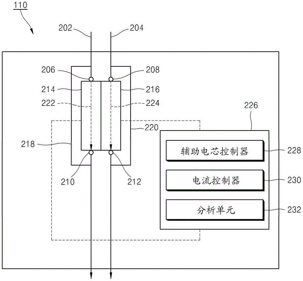
[0049] The analysis module 226 analyzes the second electrolyte solution flowing into the second auxiliary cell 216 through the following process.
[0050] 1) The auxiliary cell controller 228 opens all the valves 206 , 208 , 210 , 212 to allow the first electrolyte solution and the second electrolyte solution to flow into the first auxiliary cell 214 and the second auxiliary cell 216 . in which except figure 2 In other examples where a separate internal line is further formed as described above in addition to the internal lines 222, 224 shown in , the auxiliary cell controller 228 may also allow the electrolyte solution with the same polarity to flow into the first auxiliary cell 214 and the second auxiliary cell 216 in.
[0051] 2) The auxiliary cell controller 228 closes the valves 208 , 212 to confine the second electrolyte solution in the second auxiliary cell 216 . In other examples, the auxiliary cell controller 228 may also close all the valves 206 , 208 , 210 , 212 ...
example 2
[0077] The analysis module 226 analyzes the first electrolyte solution flowing into the first auxiliary cell 214 through the following process. The analysis process in Example 2 is performed similarly to that in Example 1.
[0078] 1) The auxiliary cell controller 228 opens all the valves 206 , 208 , 210 , 212 to allow the first electrolyte solution and the second electrolyte solution to flow into the first auxiliary cell 214 and the second auxiliary cell 216 . in which except figure 2 In other examples where a separate internal line is further formed as described above in addition to the internal lines 222, 224 shown in , the auxiliary cell controller 228 may also allow the electrolyte solution with the same polarity to flow into the first auxiliary cell 214 and the second auxiliary cell 216 middle.
[0079] 2) The auxiliary cell controller 228 closes the valves 206 , 210 to confine the first electrolyte solution in the first auxiliary cell 214 . In other examples, the au...
example 3
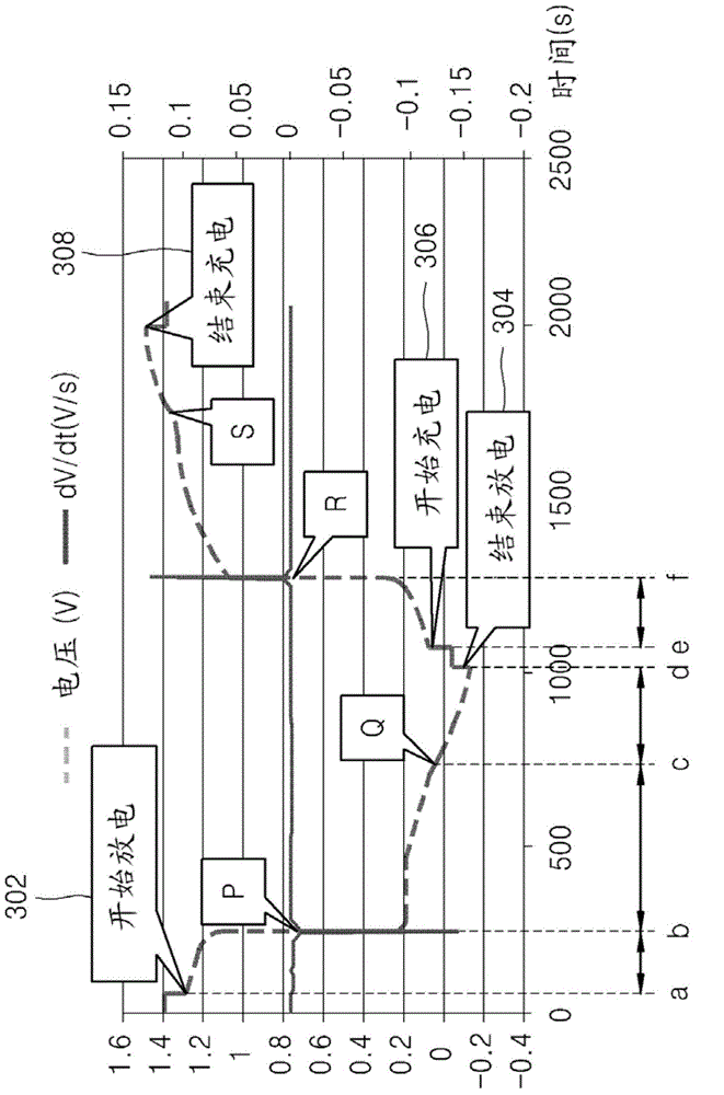
[0106] The analysis module 226 analyzes the second electrolyte solution flowing into the second auxiliary cell 216 through the following process. Figure 5 A graph created by the following procedure is shown.
[0107] 1) The auxiliary cell controller 228 opens all the valves 206 , 208 , 210 , 212 to allow the first electrolyte solution and the second electrolyte solution to flow into the first auxiliary cell 214 and the second auxiliary cell 216 . in which except figure 2 In other examples where a separate internal line is further formed as described above in addition to the internal lines 222, 224 shown in , the auxiliary cell controller 228 may also allow the electrolyte solution with the same polarity to flow into the first auxiliary cell 214 and the second auxiliary cell 216 .
[0108] 2) The auxiliary cell controller 228 closes the valves 208 , 212 to confine the second electrolyte solution in the second auxiliary cell 216 . In other examples, the auxiliary cell control...
PUM
 Abstract
Description
Claims
Application Information
 - Generate Ideas
- Intellectual Property
- Life Sciences
- Materials
- Tech Scout
- Unparalleled Data Quality
- Higher Quality Content
- 60% Fewer Hallucinations
Browse by: Latest US Patents, China's latest patents, Technical Efficacy Thesaurus, Application Domain, Technology Topic, Popular Technical Reports.
© 2025 PatSnap. All rights reserved.Legal|Privacy policy|Modern Slavery Act Transparency Statement|Sitemap|About US| Contact US: help@patsnap.com


