
A fire resistance test device and method capable of providing axial elastic restraint of components

A technology of elastic restraint and test device, which is applied in the testing, measuring device, instrument of machine/structural components, etc., can solve the problems of inability to study the mechanical behavior characteristics of components, inability to provide elastic restraint, and small length of test specimens. Fast installation, convenient disassembly and assembly, and the effect of increasing the utilization rate

Inactive Publication Date: 2017-03-01
NANJING TECH UNIV
View PDF8 Cites 0 Cited by
  • Summary
  • Abstract
  • Description
  • Claims
  • Application Information

AI Technical Summary

Problems solved by technology

[0004] In the current domestic and foreign fire resistance tests, simply supported H-shaped steel beams are generally used to provide restraint, but there are two problems with this device: 1. The restraint stiffness provided by the H-shaped steel beam is obtained from the section characteristics of the steel beam, which is not easy to be accurate Obtain the restraint stiffness that meets the test requirements; 2. When the H-shaped steel beam has a small deflection in the mid-span, it will produce plastic deformation, and cannot provide continuous elastic restraint during the test
These problems lead to the short length of the test specimen, and at the same time, only the mechanical response of the specimen before buckling and during buckling can be studied, and the mechanical behavior characteristics of the component after buckling and during the cooling process cannot be studied

Method used


Image

  • A fire resistance test device and method capable of providing axial elastic restraint of components
  • A fire resistance test device and method capable of providing axial elastic restraint of components
  • A fire resistance test device and method capable of providing axial elastic restraint of components

Examples


Embodiment Construction

[0035] The present invention will be further described below in conjunction with the accompanying drawings and specific embodiments.

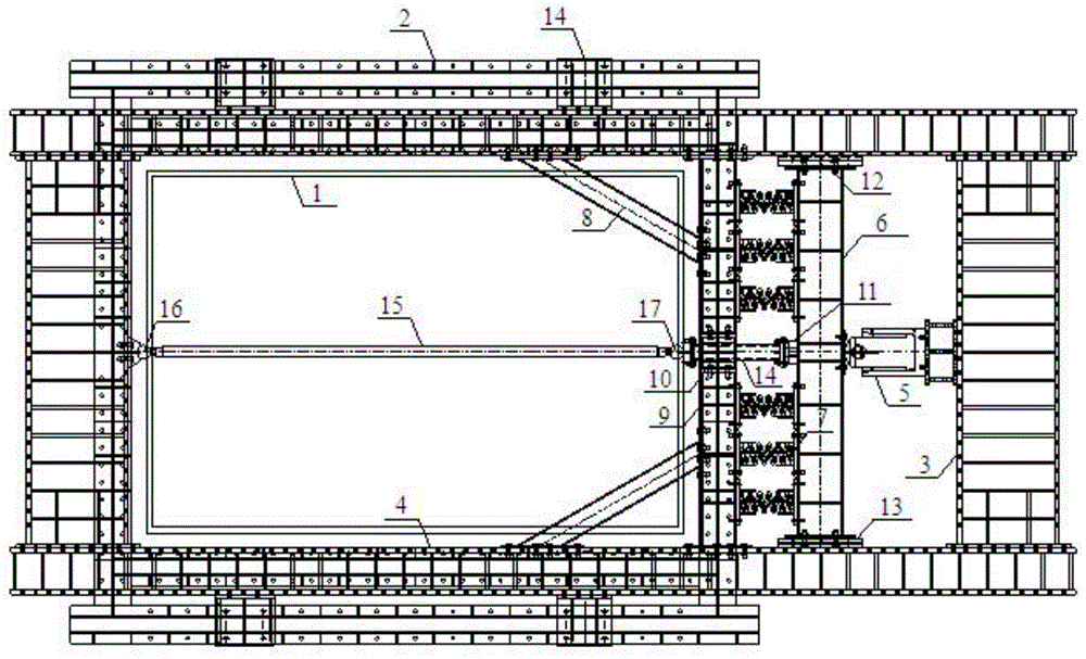
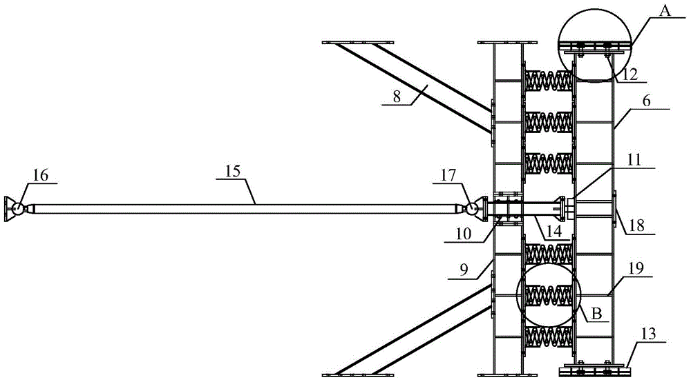
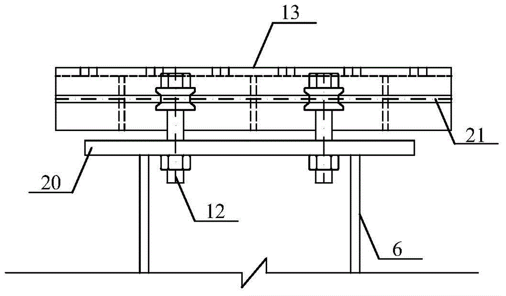
[0036] Such as Figure 1-6 As shown, a fire resistance test device that can provide axial elastic restraint of components includes a test furnace 1, a frame beam 2 on the top of the furnace, a reaction force frame, a hydraulic jack 5, a sliding beam 6, a combined spring, an auxiliary reaction force frame, a pressure Sensor 11, bolt type roller bearing 12, channel steel 13, loading column 14, test piece 15, test piece support one 16, test piece support two 17;

[0037] Described reaction force frame comprises reaction force frame crossbeam 3 and reaction force frame column 4, and described reaction force frame beam 3 is fixed between two reaction force frame columns 4, and reaction force frame column 4 is fixed on test stove by fixed support 1 on the stove top frame beam 2;

[0038] The hydraulic jack 5 is fixed on the inner side of the reacti...


PUM


Abstract

The invention discloses a fire-resistance experiment device and method capable of providing the axial elastic restraint for a component. The fire-resistance experiment device comprises a sliding beam, a combined spring, an auxiliary reaction frame, a loading pillar, a pressure sensor, a sliding support, a test piece support and a plurality of other joint connection forms, wherein the auxiliary reaction frame comprises a beam, a mid-span assembly and support pillars. One integral set of fire-resistance experiment device can be assembled by matching of the fire-resistance experiment device and existing experimental furnace, reaction frame and hydraulic jack. By utilizing the device, an axially restrained component and particularly a large slenderness ratio axially-restrained component can be researched; restraint rigidity is accurately controlled; data, such as a temperature, an axial force and a displacement, of the restrained component before fired buckling, in the fired buckling process, after fired buckling and even in the whole process of the temperature reduction stage is acquired; the foundation is laid for researching the mechanical property, the deformational behavior, the failure characteristic and the like of the restrained component in a fired state.

Description

technical field [0001] The invention relates to the field of fire resistance tests of building structures, in particular to a fire resistance test device and method capable of providing axial elastic constraints of components. Background technique [0002] Since the 1990s, the research on structural fire resistance has progressed from independent components to the experimental and theoretical research on the fire resistance of components based on structural continuity. Numerous research results have shown that due to the continuity of the structure, the mutual constraints between components will have two effects. On the one hand, it will constrain the axial expansion of the components and reduce the critical temperature of the components; on the other hand, when the components buckle, the constraints will To share the lost bearing capacity of the member, it is shown that the member has a certain post-buckling strength. For example, in a large-space building fire scene, due ...

Claims


Application Information

Patent Timeline
Patent Type & Authority Patents(China)
IPC IPC(8): G01M99/00G01N25/00
Inventor 杜咏张永振
Owner NANJING TECH UNIV
Learn More