Eureka AIR delivers breakthrough ideas for toughest innovation challenges, trusted by R&D personnel around the world.

Sewage drainage device

A technology for sewage devices and sewage pits, which is applied to water supply devices, drainage structures, waterway systems, etc., can solve the problems of poor anti-pollution ability, low degree of automation, easy backflow of oil, etc., and achieves easy maintenance, reliable performance, and application range. wide range of effects

Inactive Publication Date: 2015-06-03
大连维乐液压制造有限公司
View PDF7 Cites 3 Cited by
  • Summary
  • Abstract
  • Description
  • Claims
  • Application Information

AI Technical Summary

Problems solved by technology

[0003] The technical problem to be solved by the present invention is to provide a sewage discharge device to solve the problems of poor anti-pollution ability, small head, small flow, easy backflow of oil, and low degree of automation

Method used


Image

  • Sewage drainage device
  • Sewage drainage device
  • Sewage drainage device

Examples


Embodiment Construction

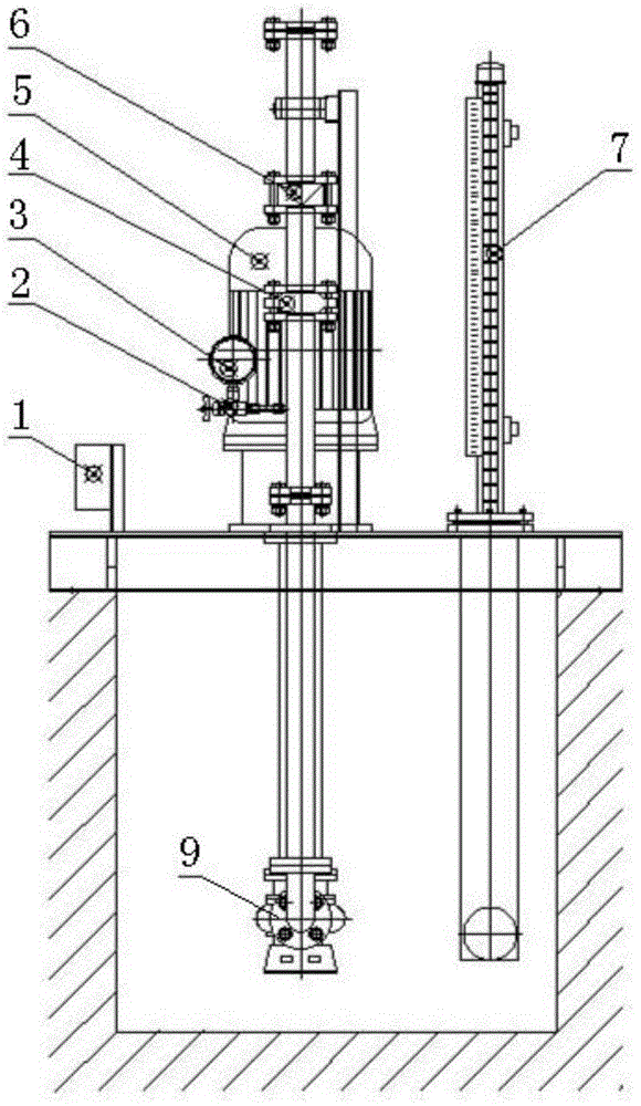
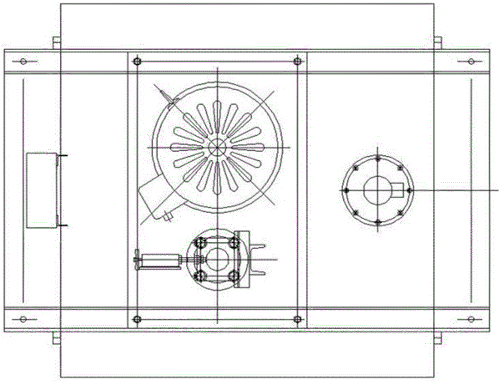
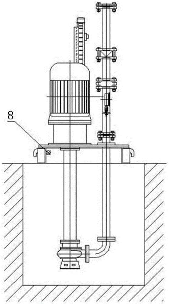
[0012] Such as Figure 1-Figure 4 As shown, the sewage discharge device includes a motor 5, a check valve 6, a magnetic float level gauge 7, a support 8 and a submerged centrifugal pump 9, the support 8 is installed above the sump, and the upper middle part of the support 8 is installed There is a motor 5, and the motor 5 is connected to the submerged centrifugal pump 9 located in the sewage pit. The submerged centrifugal pump 9 is connected to the butterfly valve 4 and the check valve 6 in sequence through the pipeline through the support 8, and the butterfly valve 4 and the support 8 A pressure gauge switch 2 and a pressure gauge 3 are installed on the pipeline. The pressure gauge 3 is a shock-resistant pressure gauge. The terminal box 1 is installed on the upper side of the support 8, and the magnetic float level gauge 7 is installed on the other side. The bottom of the position meter 7 passes through the support 8 and is located in the sewage pit; the present invention has...


PUM


Abstract

The invention discloses a sewage drainage device. A support is installed above a sewage pit, a motor is installed in the middle of the upper surface of the support and is connected to a subsurface centrifugal pump in the sewage pit, the subsurface centrifugal pump penetrates the support to connect to a butterfly valve and a check valve through a pipeline, and a pressure gauge switch and a pressure gauge are installed on the pipeline between the butterfly valve and the check valve; a terminal case is installed on one side of the upper surface of the support, the other side is provided with a magnetic float level gauge, and the bottom of the magnetic float level gauge penetrates the support to locate into the sewage pit. The device has fine contamination resistance, large stroke and flow and wide application range; the magnetic float level gauge can be used for observing the sewage level in real time, automatic pumping stop is implemented through electrical control, and automatic control is implemented; the check valve is adopted, so that oil backflow due to the gravity can be prevented; the electrical control and manual control are adopted, and the on-site requirements are met well.

Description

technical field [0001] The invention relates to the technical field of sewage treatment, in particular to a sewage discharge device. Background technique [0002] In the prior art, the equipment for removing sewage has a wide range of applications, but has poor anti-pollution ability, small head, small flow rate, easy backflow of oil, and low degree of automation, which cannot well meet the needs of the site. Contents of the invention [0003] The technical problem to be solved by the present invention is to provide a sewage discharge device to solve the problems of poor anti-pollution ability, small head, small flow rate, easy backflow of oil, and low degree of automation. [0004] In order to solve the above-mentioned technical problems, the technical solution of the present invention is: the sewage discharge device includes a motor, a check valve, a magnetic float liquid level gauge, a support and a submerged centrifugal pump, the support is installed above the sewage p...

Claims


Application Information

Patent Timeline
Patent Type & Authority Applications(China)
IPC IPC(8): E03F5/22
CPCE03F5/22
Inventor 丁维力夏正国
Owner 大连维乐液压制造有限公司
Why Eureka
Eureka Blog
Learn More