Dissolved air tank with adjustable vapor liquid ratio

A technology of dissolved air tank and gas-liquid ratio, applied in the direction of flotation water/sewage treatment, etc., can solve the problems of reducing air flotation effect, unsatisfactory treatment effect, and unsuitable impact of air flotation machine, so as to improve the efficiency of dissolved air. Effect

Inactive Publication Date: 2015-06-03
大庆市海油庆石油科技有限公司
View PDF7 Cites 4 Cited by
  • Summary
  • Abstract
  • Description
  • Claims
  • Application Information

AI Technical Summary

Problems solved by technology

[0002] The maximum solubility of air in water mainly depends on the pressure, water temperature and water quality. The higher the pressure and the lower the water temperature, the greater the saturation solubility of air in water. According to the properties of gas and liquid, and the change of temperature and pressure, gas in liquid The saturation solubility in the air is different. In order to capture the suspended matter as much as possible, the air bubbles in the air flotation should be as small as possible and distributed evenly. At present, the saturation solubility of gas (air) in water depends on the temperature and pressure of the water. The saturation solubility of gas (air) in water under temperature and pressure conditions is also different. The gas-liquid ratio adjusted by the multiphase pump used in the air flotation machine is mostly adjusted by manually adjusting the pressure, vacuum degree, gas flow rate, and circulating water flow rate of the pump. The gas-liquid ratio is controlled, and the circulating water is set relative to the total water inflow. The dissolved air system cannot respond accordingly to the water quality and water volume changes of the sewage, thereby reducing the air flotation effect and making the air flotation machine no longer To adapt to the impact brought by changes in water quality and treatment volume, the treatment effect is not ideal

Method used


Image

  • Dissolved air tank with adjustable vapor liquid ratio
  • Dissolved air tank with adjustable vapor liquid ratio

Examples


Embodiment Construction

[0010] The present invention will be further described below in conjunction with accompanying drawing:

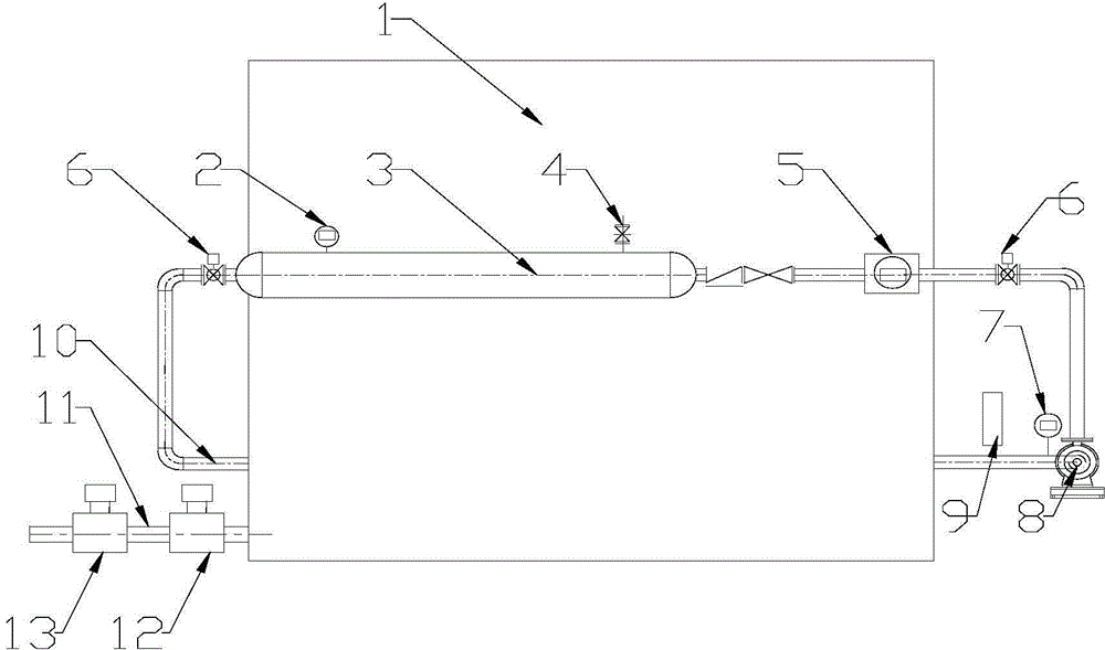
[0011] Depend on figure 1 As shown, the dissolved air tank with adjustable gas-liquid ratio includes an air flotation tank 1, the bottom of the water outlet part of the air flotation tank 1 is led out by a pipeline, and then connected in series with a dissolved air pump 8, an electric regulating valve 6, a circulating water flow meter 5, a gate valve, The check valve, the dissolved air tank 3, and the electric regulating valve 6 adjust the pressure and flow of the dissolved gas tank 3. The outlet side pipeline of the dissolved gas tank 3 is connected in series with an electric regulating valve 6 and then connected to the release pipe 10, which is located above the water inlet pipe 11. . The water inlet pipe 11 is connected in series with an online turbidimeter 13 and an inlet water flow meter 12 . The present invention sets the circulating water flow rate required by the ...


PUM


Abstract

The invention provides a dissolved air tank with an adjustable vapor liquid ratio. A dissolved air pump, electric control valves, a circulating water flowmeter, a brake valve, a check valve and a dissolved air tank are connected in series through a pipeline of an air floating system; a pipeline at the outlet side of each dissolved air pump is connected in series with the electric control valve, and then connected with a relief pipe; a water inlet pipe is connected in series with an online turbidity meter and a water inlet flowmeter; an automatic air inflow regulating valve and a vacuum pressure sensor are connected with the pipeline at the inlet side of the dissolved air pump; a pressure sensor and an automatic air exhausting device are arranged at the upper part of the dissolved air tank. The flowmeter and the control valves are additionally arranged in the dissolved air system of the air floating machine, and meanwhile the online turbidity meter and the flowmeter are mounted at the water inlet side, so that the vapor liquid ratio can be automatically adjusted to be adapted to the water inlet quality and the flow change, and the air dissolving efficiency can be improved.

Description

Technical field: [0001] The invention relates to the technical field of sewage treatment, in particular to an air-dissolving tank with an adjustable gas-liquid ratio. Background technique: [0002] The maximum solubility of air in water mainly depends on the pressure, water temperature and water quality. The higher the pressure and the lower the water temperature, the greater the saturation solubility of air in water. According to the properties of gas and liquid, and the change of temperature and pressure, gas in liquid The saturation solubility in the air is different. In order to capture the suspended matter as much as possible, the air bubbles in the air flotation should be as small as possible and distributed evenly. At present, the saturation solubility of gas (air) in water depends on the temperature and pressure of the water. The saturation solubility of gas (air) in water under temperature and pressure conditions is also different. The gas-liquid ratio adjusted by t...

Claims


Application Information

Patent Timeline
Patent Type & Authority Applications(China)
IPC IPC(8): C02F1/24
Inventor 刘萍王向东柳国政
Owner 大庆市海油庆石油科技有限公司
Why Eureka
Try Eureka