Little finger force feedback device
A feedback device, little finger technology, applied in manipulators, manufacturing tools, etc., can solve the problems of complex system, difficult maintenance, and expensive force feedback data gloves, etc.
- Summary
- Abstract
- Description
- Claims
- Application Information
AI Technical Summary
Problems solved by technology
Method used
Image
Examples
specific Embodiment approach 1
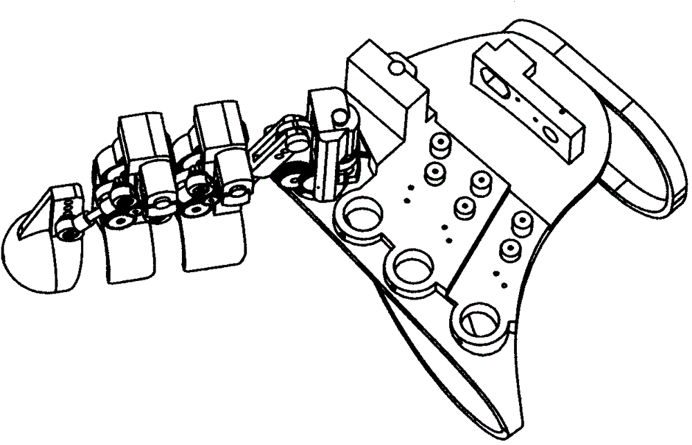
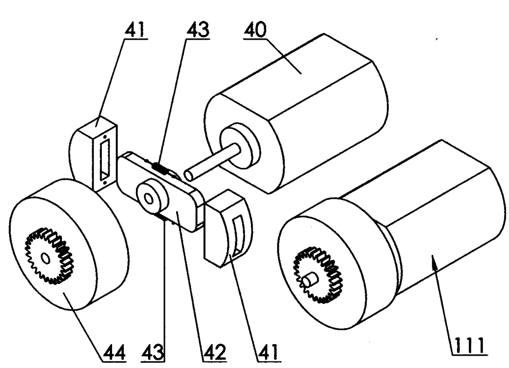
[0018] Specific implementation mode one: as figure 2 As shown, the little finger force feedback device includes a driving part 111, and the driving part 111 includes a micro motor 40 and a clutch, and the clutch is composed of a clutch friction plate 41, a friction plate slide bar 42, a return tension spring 43, and a clutch cover 44. The friction plate slide bar 42 is fixedly connected to the shaft of the micro motor 40, the two clutch friction plates 41 are inserted into the two ends of the friction plate slide bar 42 respectively, and a return tension spring 43 is connected between the two clutch friction plates 41, and the clutch The cover 44 is inserted into the shaft of the micro motor 40, and the clutch cover 44 is in sliding contact with the shaft of the micro motor 40, and the clutch cover 44 is provided with transmission gears. Action implementation process: when the rotation speed of the micro motor 40 is higher than a certain value, the two clutch friction plates ...
specific Embodiment approach 2
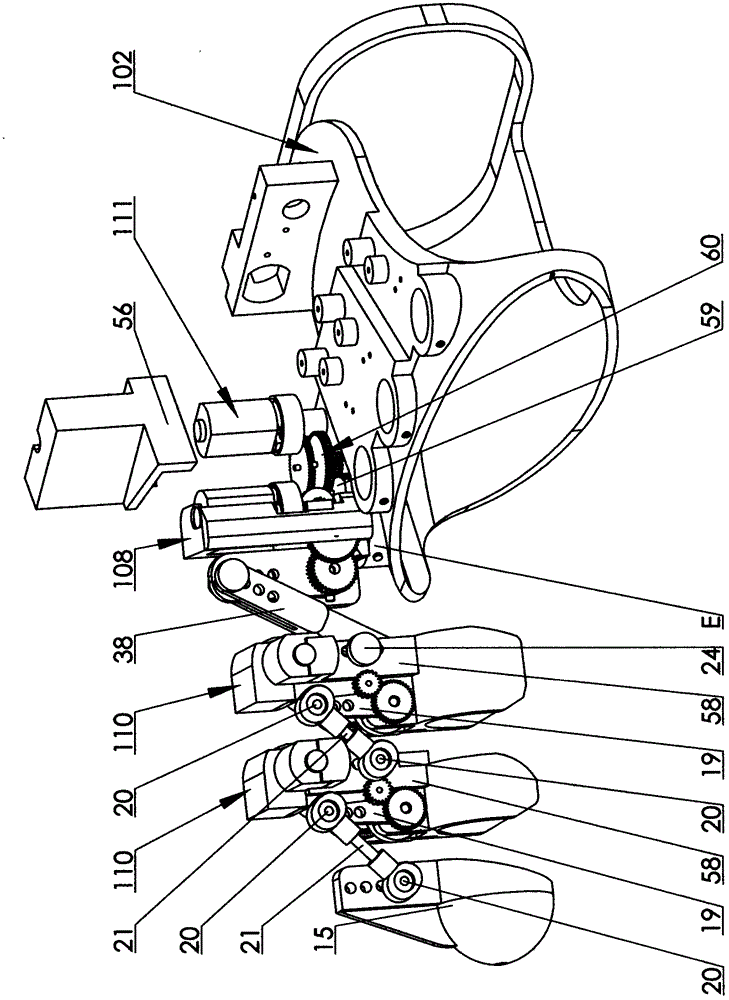
[0019] Specific implementation mode two: as figure 1 , Figure 4 and Figure 5 As shown, the metacarpophalangeal joint detection driving mechanism 108 includes a driving component 111 , a rocker arm 27 , a metacarpophalangeal joint base 29 , a connecting rod 38 , a gear case cover 50 and two angle sensors 18 . The bottom of metacarpophalangeal joint base 29 (embedded bearing 39) is affixed to the shaft of an angle sensor 18 by screws 36, and said metacarpophalangeal joint base 29 can rotate around the axis of bottom angle sensor 18. The outer edge of the base 29 bottom is provided with a gear 59, the axis of the gear 59 coincides with the axis of the angle sensor 18 at the bottom of the metacarpophalangeal joint base 29, and another angle sensor 18 is fixed on the bottom of the metacarpophalangeal joint base 29 by a screw 35. In the hole seat L, the shaft of the angle sensor 18 and one end of the rocking arm 27 (embedded bearing 23) are fixedly connected by a screw 36, and t...
specific Embodiment approach 3
[0020] Specific implementation mode three: as figure 1 , Figure 6 and Figure 7 As shown, the little finger joint detection driving mechanism 110 includes a driving component 111 , an angle sensor 18 , a rocker arm 19 , a gear case cover 57 and a knuckle base 58 . The knuckle base 58 is provided with a hole seat P and a row of mounting holes R for the screws 24, the angle sensor 18 is fixed in the hole seat P of the knuckle base 58 by screws 36, and the hole seat The shaft of the angle sensor 18 in the P is fixedly connected with the rocking arm 19 by a screw 35, and the gear axis on the rocking arm 19 coincides with the axis of the rocking arm rotation, and the gear of the rocking arm 19 passes through the reduction gear set 60. Cooperate with the gear of the driving part 111 , the driving part 111 is installed on the knuckle base 58 , and the other end of the rocker arm 19 is fixedly connected to the ball head 20 .
PUM
 Abstract
Description
Claims
Application Information
 - R&D Engineer
- R&D Manager
- IP Professional
- Industry Leading Data Capabilities
- Powerful AI technology
- Patent DNA Extraction
Browse by: Latest US Patents, China's latest patents, Technical Efficacy Thesaurus, Application Domain, Technology Topic, Popular Technical Reports.
© 2024 PatSnap. All rights reserved.Legal|Privacy policy|Modern Slavery Act Transparency Statement|Sitemap|About US| Contact US: help@patsnap.com


