
Angle-adjusting numerical control machine tool combined clamp

A technology of CNC machine tools and combined fixtures, which is applied in the direction of clamping, manufacturing tools, metal processing machinery parts, etc., can solve the problems that the precision of combined fixtures is difficult to reach a higher level, shorten the production preparation cycle, and have positioning errors.

Active Publication Date: 2015-06-03
ANHUI TECHN COLLEGE OF MECHANICAL & ELECTRICAL ENG
View PDF4 Cites 12 Cited by
  • Summary
  • Abstract
  • Description
  • Claims
  • Application Information

AI Technical Summary

Problems solved by technology

Such a structure can save man-hours for fixture manufacturing and shorten the production preparation cycle. Since the lower base plate and the upper base plate are hinged, there are positioning errors, and the accuracy of the combined fixture is difficult to reach a higher level.

Method used


Image

  • Angle-adjusting numerical control machine tool combined clamp
  • Angle-adjusting numerical control machine tool combined clamp
  • Angle-adjusting numerical control machine tool combined clamp

Examples


Embodiment Construction

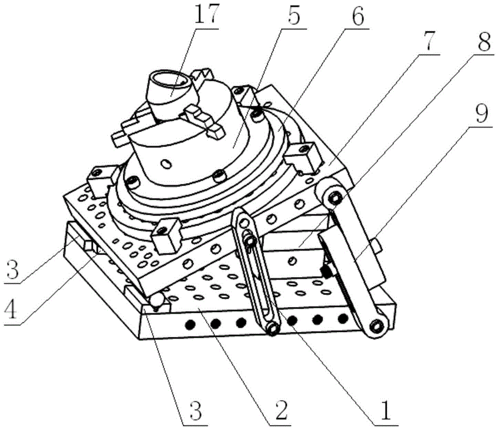
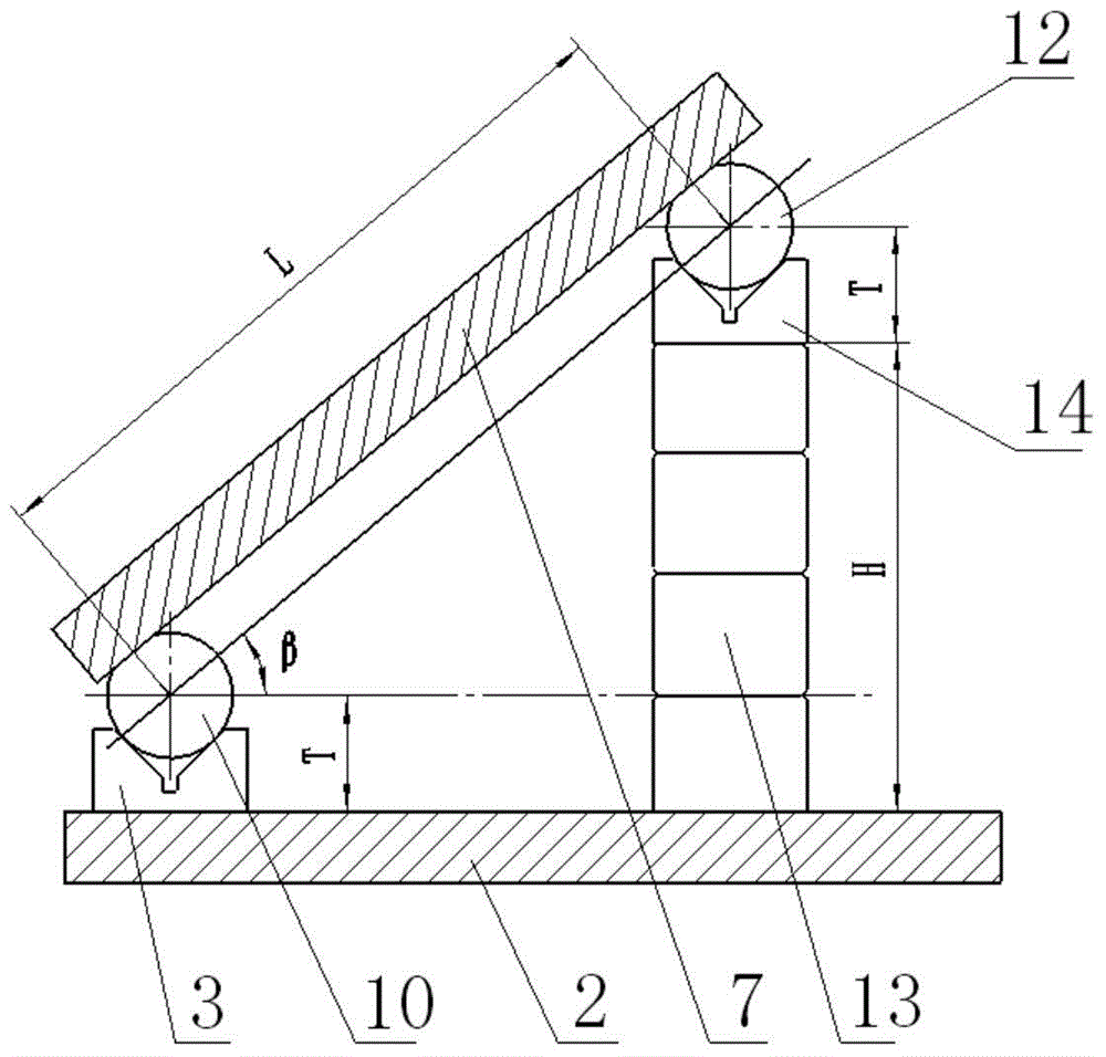
[0018] like figure 1 , figure 2 , image 3 , Figure 4 As shown, an angle-adjustable CNC machine tool combination fixture of the present invention includes a lower base plate 2, an upper base plate 7, a first connecting plate 1, a second connecting plate 9, a support member 8, an indexing plate 6 and a three-jaw chuck 5. The three-jaw chuck 5 is located above the upper base plate 7, and the workpiece 17 is clamped by the three-jaw chuck 5. There is an indexing plate 6 between the three-jaw chuck 5 and the upper base plate 7, and the holes on the upper base plate 7 The system consists of pin holes and bolt connection holes evenly distributed on the circumference of three different diameters, which is convenient for indexing and positioning. The support is vertically fixed on the lower base plate 2, and the lower base plate 2 is arranged near one side with two identical low V-shaped support blocks 3 whose centerlines coincide. The support 8 is composed of a rectangular suppo...


PUM


Abstract

The invention discloses an angle-adjusting numerical control machine tool combined clamp which comprises a lower base plate, an upper base plate, a connecting plate, a support part and a three-jaw chuck. The support part is vertically fixed on the lower base plate. The lower base plate is provided with two identical low-position V-shaped support blocks close to one side. The central lines of the two V-shaped support blocks coincide. The support part comprises a rectangular support element and a high-position V-shaped support block. The high-position V-shaped support block and the low-position V-shaped support blocks are identical in structure. One downward face of the upper base plate is provided with three trimming shafts forming a triangle. The trimming shafts are identical in structure and integrally connected with the upper base plate. The three trimming shafts are respectively located on the two low-position V-shaped support blocks and the high-position V-shaped support block. By the structure, the angle-adjusting numerical control machine tool combined clamp has the advantages that the precision of the clamp is increased greatly, clamp manufacturing time can be reduced, production preparation cycle can be shortened, machining efficiency is increased, and manufacturing cost is lowered.

Description

technical field [0001] The invention relates to a fixture, in particular to an angle-adjustable combined fixture for a numerically controlled machine tool. Background technique [0002] With the advancement of modern science and technology and the rapid development of productivity, the types of mechanical and electrical products are changing with each passing day, which has prompted obvious changes in the form of manufacturing and processing in the machinery industry. In the modern machinery manufacturing industry, machining machine tools and machine tool fixtures are required to be widely adapted. In recent years, the rapid development of CNC machine tools and flexible manufacturing systems is meeting the needs of multi-variety and small batch production methods. In this production method, combined fixtures, adjustable fixtures and other combined and adjustable features The flexible fixture system has been widely used; combined fixtures are prefabricated components and asse...

Claims


Application Information

Patent Timeline
IPC IPC(8): B23Q3/04B23B31/10
CPCB23Q3/04
Inventor 徐亮杜文文方慧敏徐小飞肖文林陈健钱金鑫刘珩
Owner ANHUI TECHN COLLEGE OF MECHANICAL & ELECTRICAL ENG
Learn More