Bending equipment

A kind of equipment and bending arm technology, applied in the direction of heat exchange equipment, etc., can solve the problems of poor quality of evaporator, increase of enterprise cost, inconvenient transportation, etc., and achieve the effect of high processing efficiency, improved precision and convenient transportation

Active Publication Date: 2015-06-03
浙江长兴和良智能装备有限公司
View PDF6 Cites 12 Cited by
  • Summary
  • Abstract
  • Description
  • Claims
  • Application Information

AI Technical Summary

Problems solved by technology

[0003] The production process of the micro-channel evaporator includes many processes. After many processes, the formed evaporator is obtained. The final process is bending. However, in the prior art, especially in my country, many evaporators sold abroad are transported After arriving all over the world, the processing of the bending process is carried out, which is inconvenient for transportation and greatly increases the cost of transportation, thereby increasing the cost of the enterprise
Therefore, it is necessary for the development of evaporators in my country to complete the bending of the evaporator and then sell it. However, the quality of the evaporator obtained by bending the existing bending equipment is poor. Good quality bending equipment is particularly important

Method used


Image

  • Bending equipment
  • Bending equipment
  • Bending equipment

Examples


Embodiment Construction

[0039] In order to make the purpose, technical solutions and advantages of the embodiments of the present invention more clear, the following will clearly and completely describe the technical solutions of the embodiments of the present invention in conjunction with the drawings of the embodiments of the present invention. Apparently, the described embodiments are some, not all, embodiments of the present invention. Based on the described embodiments of the present invention, all other embodiments obtained by persons of ordinary skill in the art without creative efforts shall fall within the protection scope of the present invention.

[0040] In describing the present invention, it should be understood that the terms "center", "longitudinal", "transverse", "length", "width", "thickness", "upper", "lower", "front", " Orientation or position indicated by "back", "left", "right", "vertical", "horizontal", "top", "bottom", "inner", "outer", "clockwise", "counterclockwise", etc. T...


PUM


Abstract

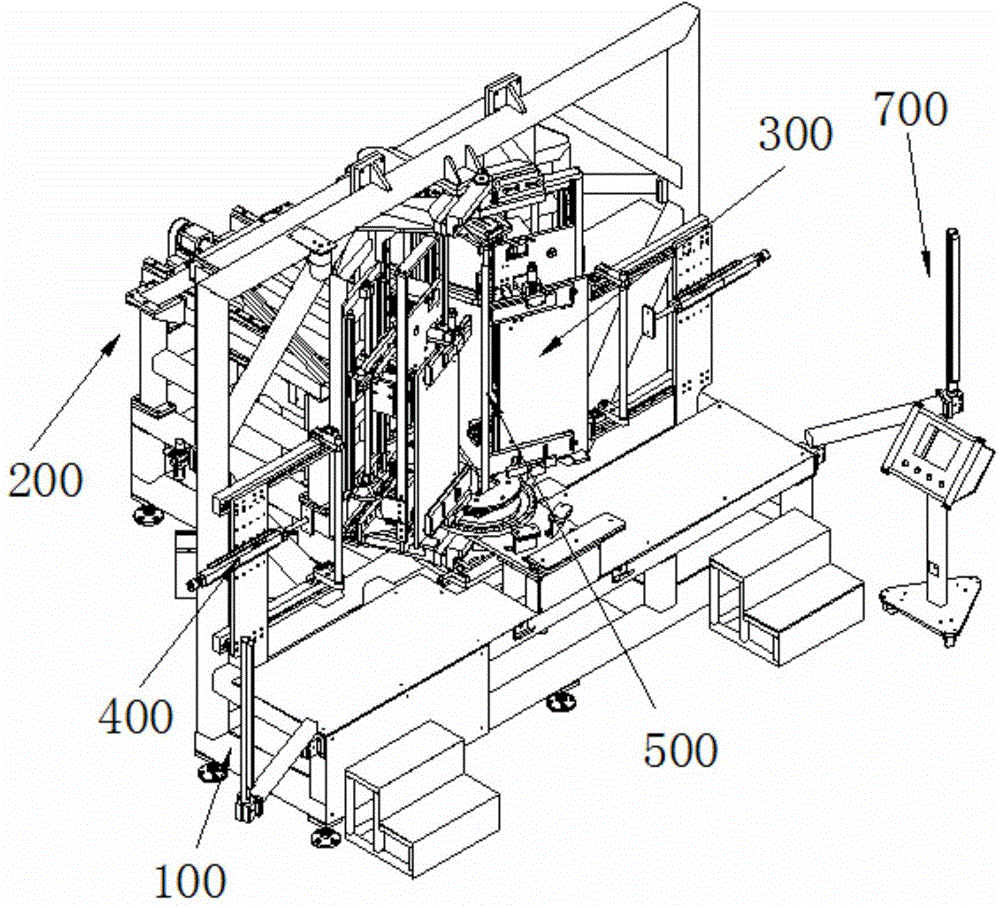
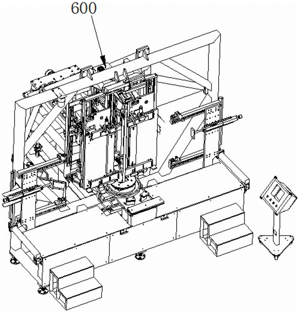
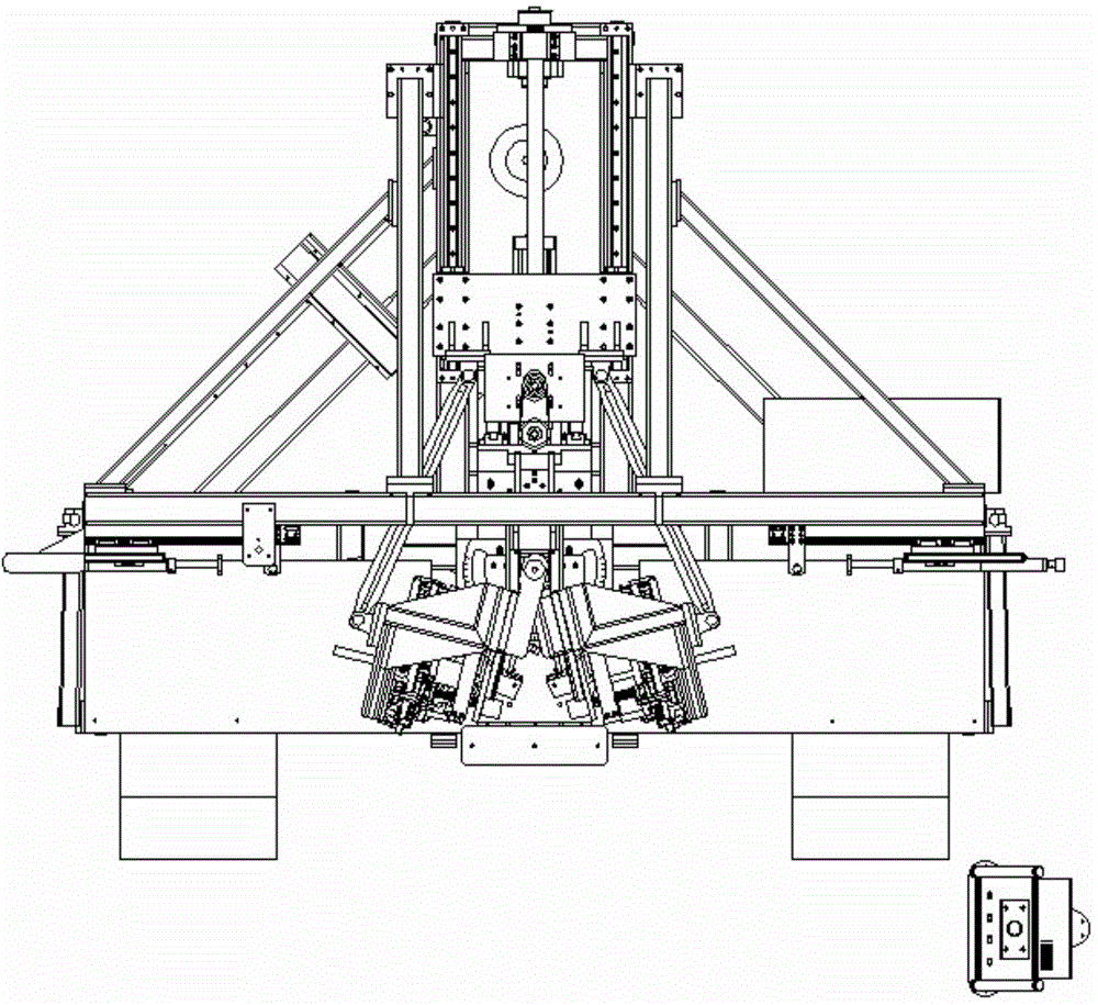
The invention discloses bending equipment, which comprises a rack, a bending mechanism and a clamping mechanism, wherein the bending mechanism and the clamping mechanism are arranged on the rack, the bending mechanism is used for bending a workpiece, and the clamping mechanism is used for clamping the workpiece; the bending mechanism comprises a pair of bending arm assemblies, a rotating shaft, a bending driving device and a permanent seat, wherein the bending arm assemblies are symmetrically arranged, the rotating shaft is fixedly connected with the rack, the bending driving device is used for driving the bending arm assemblies to rotate relative to the rotating shaft to bend the workpiece, and the permanent seat is fixedly connected with the rack; the bending driving device comprises bending connecting rods, a sliding table and bending driving assemblies, wherein the sliding table is glidingly connected with the permanent seat, and the bending driving assemblies are used for driving the sliding table to slide relative to the permanent seat; one end of each bending connecting rod is connected with the corresponding bending arm assembly, and the other end of each bending connecting rod is connected with the sliding table; the sliding table is driven to relatively slide through the bending driving assemblies to drive the bending connecting rods to be linked to realize bending of the bending arm assemblies. According to the bending equipment provided by the invention, bending on an evaporator can be automatically finished, so that the work efficiency is greatly increased, the bent evaporator is convenient to transport, and the cost is greatly reduced.

Description

technical field [0001] The invention relates to mechanical equipment, in particular to a bending equipment. Background technique [0002] The evaporator is a partitioned heat exchange device. Its working principle is: the low-temperature and low-pressure liquid refrigerant gasifies and absorbs heat on one side of the heat transfer wall, so that the medium on the other side of the heat transfer wall is cooled. At present, in mechanical compression refrigeration equipment, heat exchange devices such as condensers and evaporators are often used to dissipate heat from the high-temperature and high-pressure refrigerant through the condenser, and then enter the room to expand and absorb heat through the evaporator, thereby achieving the cooling effect. The heat dissipation effect of the heat exchange device will directly affect the refrigeration energy efficiency of the entire refrigeration equipment. Therefore, the evaporator is an indispensable product in the refrigeration indu...

Claims


Application Information

Patent Timeline
Patent Type & Authority Applications(China)
IPC IPC(8): B21D53/02B21D11/00B21D11/22
CPCB21D11/00B21D11/22B21D53/02B21D53/022
Inventor 饶梅贵张良
Owner 浙江长兴和良智能装备有限公司
Why Eureka
Try Eureka