Voltage conversion circuit, display panel and driving method thereof
一种电压转换电路、电压的技术,应用在静态指示器、非线性光学、仪器等方向,能够解决显示面板闪烁大等问题,达到改善色偏现象、提高显示品质的效果
- Summary
- Abstract
- Description
- Claims
- Application Information
AI Technical Summary
Problems solved by technology
Method used
Image

Examples
Embodiment 1
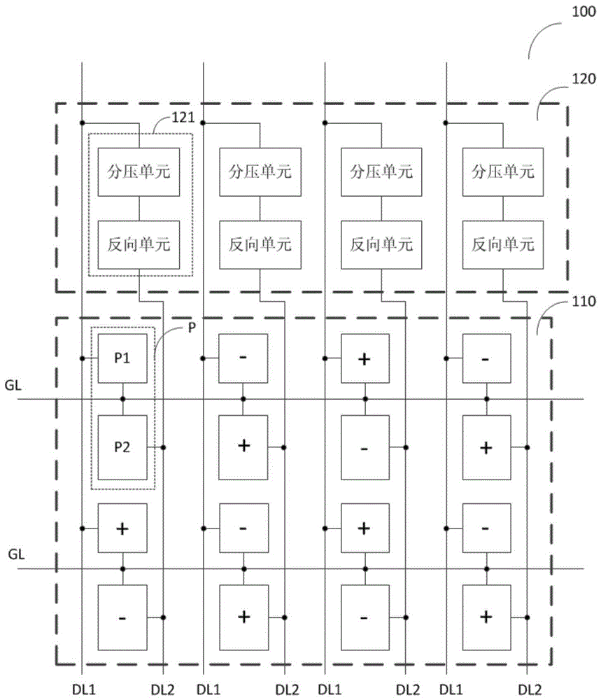
[0054] figure 1 It is a schematic diagram of the structure of the liquid crystal display panel according to this embodiment. The display panel 100 is, for example, a VA type display panel, which includes a display area 110 and a non-display area 120, wherein the non-display area 120 is located at the periphery of the display area 110. The scan line GL and the data line DL are formed on the display panel 100 along the first direction and the second direction, respectively. The scan line GL and the data line DL cross each other in the display area 110. The data line DL includes a main data line DL1 and a sub data line DL2, and the main data line DL1 and the sub data line DL2 are parallel to each other and alternately arranged. Wherein, the scan line GL is used to transmit scan driving signals, the main data line DL1 is used to transmit data signals in the main pixel area, and the secondary data line DL2 is used to transmit data signals in the sub pixel area.
[0055] The display ...
Embodiment 2
[0065] This embodiment provides a specific structure of the voltage inversion circuit. Such as Figure 4 As shown, the reverse unit includes four transistors T1, T2, T3, and T4 of the same channel type, and a capacitive element C3.
[0066] Among them, the transistor T1 is equivalent to a specific example of a sampling voltage switch, the transistor T2 is equivalent to a specific example of a reference voltage switch, the transistor T3 is equivalent to a specific example of an output voltage switch, and the transistor T4 is equivalent to a specific example of an initialization switch. The transistors T1, T2, T3, and T4 are, for example, N-type thin film transistors (TFT).
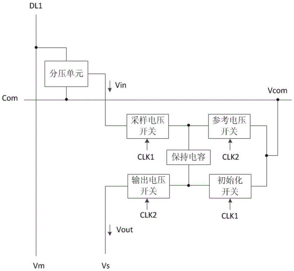
[0067] In this embodiment, the voltage dividing unit includes capacitors C1 and C2 connected in series. The input terminal of the first voltage dividing capacitor C1 is connected to the main data line DL1 and receives the data signal voltage Vm of the main pixel area; the input terminal of the second voltage di...
Embodiment 3
[0085] The difference from the second embodiment is that two transistors T1' and T4' are added to the sampling voltage switch and the initialization switch in this embodiment. Such as Figure 5 As shown, the gate and source of T1' are short-circuited and coupled to the first clock source to receive the first clock signal CLK1. The drain of T1' is coupled to the gate of T1. The gate and source of T4' are short-circuited and coupled to the first clock source to receive the first clock signal CLK1. The drain of T4' is coupled to the gate of T4.
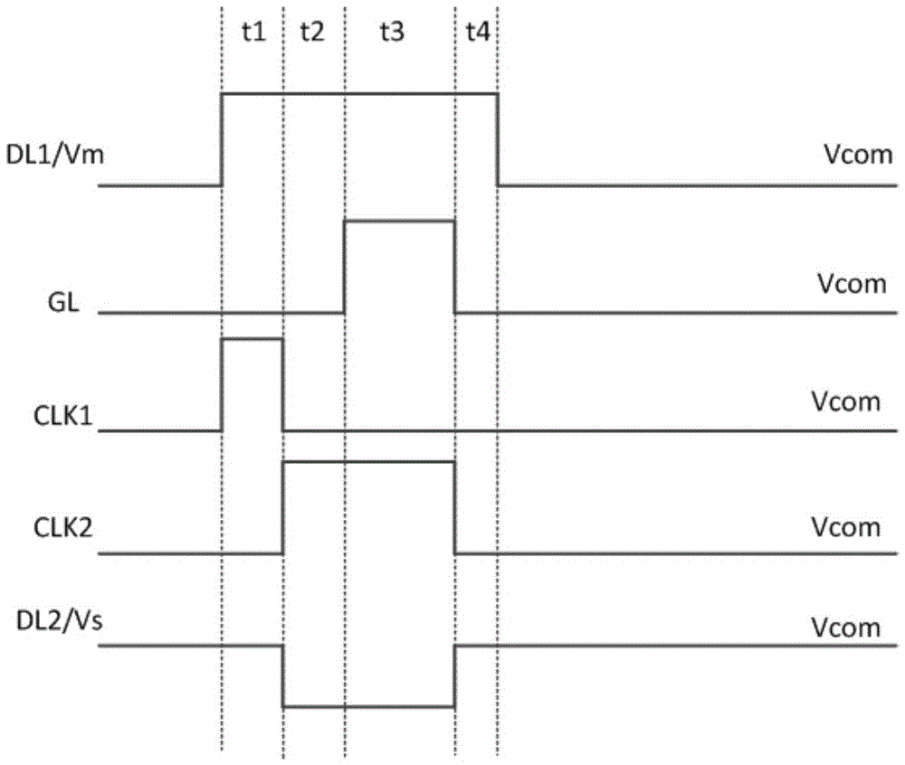
[0086] The transistors T1' and T4' can make the reverse unit work more stable. Specifically, in the t1 time period, when the first clock signal CLK1 transitions from low level to high level, the sampling voltage switch and the initialization switch can be quickly turned on, and when the first clock signal CLK1 transitions from high level to At low level, the sampling voltage switch and the initialization switch can be cut off quickly.
[...
PUM
 Abstract
Description
Claims
Application Information
 - R&D
- Intellectual Property
- Life Sciences
- Materials
- Tech Scout
- Unparalleled Data Quality
- Higher Quality Content
- 60% Fewer Hallucinations
Browse by: Latest US Patents, China's latest patents, Technical Efficacy Thesaurus, Application Domain, Technology Topic, Popular Technical Reports.
© 2025 PatSnap. All rights reserved.Legal|Privacy policy|Modern Slavery Act Transparency Statement|Sitemap|About US| Contact US: help@patsnap.com