New flocking machine head
A flocking and machine head technology, applied in the field of machinery, can solve the problems that the machine cannot be promoted and the flocking efficiency is low, and achieve the effect of novel structure, improved flocking efficiency and perfect function.
- Summary
- Abstract
- Description
- Claims
- Application Information
AI Technical Summary
Problems solved by technology
Method used
Image

Examples
Embodiment 1
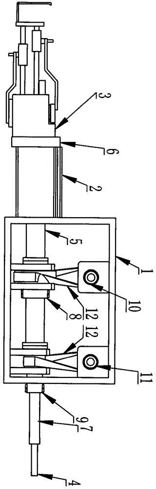
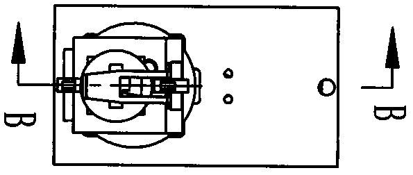
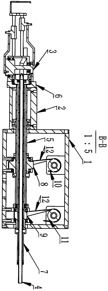
[0030] Such as Figure 1-3 As shown, a new type of flocking machine head includes a casing 1, a cylinder 2, a flocking reciprocating mechanism 3, a line pipe 4, a cylinder shaft 5, a cylinder shaft connection plate 6, a main shaft 7, a rotating synchronous wheel 8, and a main shaft synchronous Wheel 9, transmission rotation synchronous wheel 10, transmission main shaft synchronous wheel 11, synchronous belt 12, the rotation synchronous wheel 8 and the main shaft synchronous wheel 9 are arranged under the casing 1, and the transmission rotation synchronous wheel is arranged above the casing 1. Wheel 10 and the transmission main shaft synchronous wheel 11, the transmission rotation synchronous wheel 10 and the rotation synchronous wheel 8 use a synchronous belt 12 right angle transmission, the transmission main shaft synchronous wheel 11 and the main shaft synchronous wheel 9 use a synchronous belt 12 Right-angle transmission, the front end of the cylinder shaft 5 is provided wi...
Embodiment 2
[0034] Such as Figure 4-6 As shown, a new type of flocking machine head includes a casing 1, a cylinder 2, a flocking reciprocating mechanism 3, a line pipe 4, a cylinder shaft 5, a cylinder shaft connection plate 6, a main shaft 7, and a main shaft bevel gear right-angle transmission mechanism 14 1. Rotating shaft bevel gear right-angle transmission mechanism 13, the front end of the cylinder shaft 5 is provided with a cylinder shaft connection plate 6, the cylinder shaft 5 is connected to the rotating shaft bevel gear right-angle transmission mechanism 13, and the cylinder shaft 5 is connected to the rotating shaft The bevel gear right-angle transmission mechanism 13 slides and rotates at the same time. The main shaft 7 is arranged in the cylinder shaft 5. The main shaft 7 is connected to the main shaft bevel gear right-angle transmission mechanism 14. The mechanism 14 slides and rotates at the same time, the cylinder 2 is arranged in front of the casing 1, the flocking rec...
Embodiment 3
[0038] Such as Figure 7-9 As shown, a new type of flocking machine head includes a casing 1, a cylinder 2, a flocking reciprocating mechanism 3, a line pipe 4, a cylinder shaft 5, a cylinder shaft connection plate 6, a main shaft 7, and a main shaft bevel gear right-angle transmission mechanism 14 1. Rotating shaft worm gear right angle transmission mechanism 13, the front end of the cylinder shaft 5 is provided with a cylinder shaft connection plate 6, the cylinder shaft 5 is connected to the rotating shaft worm gear right angle transmission mechanism 15, and the cylinder shaft 5 is at the right angle to the rotating shaft worm gear The transmission mechanism 15 slides and rotates at the same time, the main shaft 7 is arranged in the cylinder shaft 5, the main shaft 7 is connected to the main shaft worm gear right angle transmission mechanism 16, and the main shaft 7 slides in the main shaft worm gear right angle transmission mechanism 16 while Rotate, the cylinder 2 is arra...
PUM
 Abstract
Description
Claims
Application Information
 - Generate Ideas
- Intellectual Property
- Life Sciences
- Materials
- Tech Scout
- Unparalleled Data Quality
- Higher Quality Content
- 60% Fewer Hallucinations
Browse by: Latest US Patents, China's latest patents, Technical Efficacy Thesaurus, Application Domain, Technology Topic, Popular Technical Reports.
© 2025 PatSnap. All rights reserved.Legal|Privacy policy|Modern Slavery Act Transparency Statement|Sitemap|About US| Contact US: help@patsnap.com