
Surface-mount type electric connecting terminal, electronic module unit and circuit board using the same

一种表面贴装、电连接的技术,应用在导电连接、连接装置的零部件、电路等方向,能够解决难以实现表面贴装真空拾取、柱塞60壁厚变薄、难以实现高度较等问题,达到移动顺畅、焊接强度良好、可靠焊接的效果

Active Publication Date: 2015-05-20
JOINSET +1
View PDF4 Cites 18 Cited by
  • Summary
  • Abstract
  • Description
  • Claims
  • Application Information

AI Technical Summary

Problems solved by technology

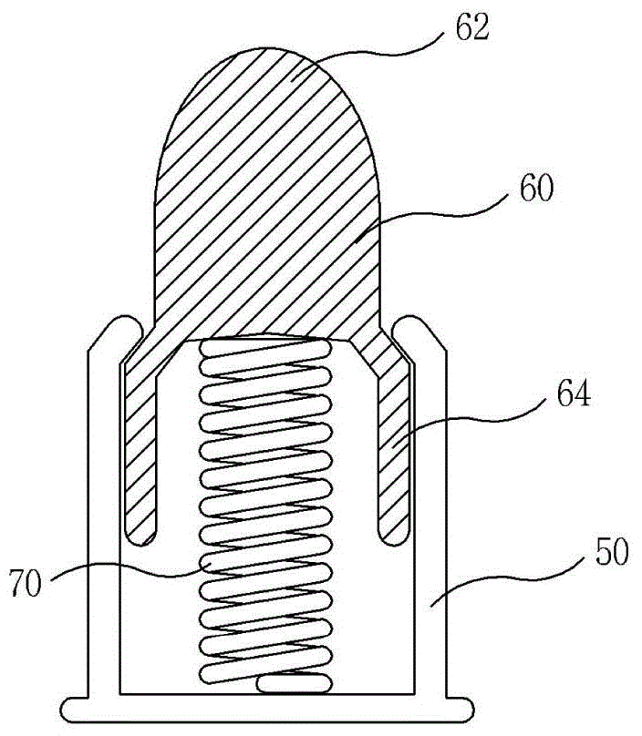
[0014] For this reason, pogo pins have the following disadvantages: it is difficult to achieve a relatively low height while moving a large distance in the vertical direction, and it is difficult to be mounted on printed circuit board
[0015] Also, since the upper surface 62 of the plunger 60 of the pogo pin is formed in a dome shape, there is a problem that it is difficult to realize vacuum pickup for surface mounting.
[0016] Moreover, the plunger 60 of the pogo pin is usually manufactured by cutting metal, so the manufacturing cost is high, and there is a limitation in making the wall thickness of the plunger 60 thinner.
[0017] In addition, since the plunger 60 formed by cutting metal is heavier than the barrel 50, the center of gravity is shifted to the upper side, and there is a disadvantage that there is a large amount of vibration during reflow soldering.

Method used


Image

  • Surface-mount type electric connecting terminal, electronic module unit and circuit board using the same
  • Surface-mount type electric connecting terminal, electronic module unit and circuit board using the same
  • Surface-mount type electric connecting terminal, electronic module unit and circuit board using the same

Examples


Embodiment Construction

[0091] Hereinafter, a surface mount type electrical connection terminal according to an embodiment of the present invention will be specifically described with reference to the drawings.

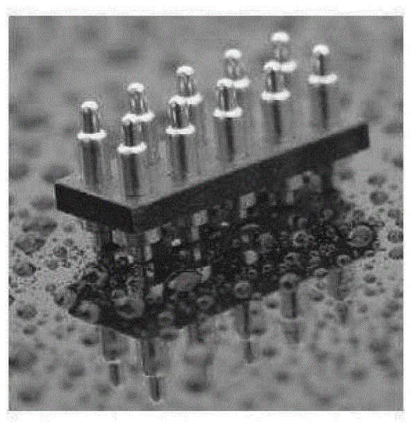
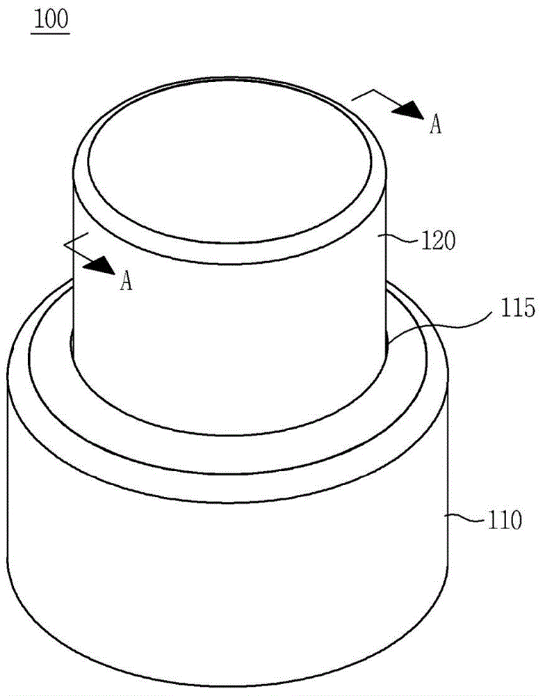
[0092] figure 2 To show a perspective view of a surface mount type electrical connection terminal according to an embodiment of the present invention, Figure 2A for along figure 2 A-A truncated cross-sectional view, image 3 (A) and (B) respectively represent the states before and after pressurizing the moving parts, Figure 4 (A) and (B) respectively represent actual product images of surface mount electrical connection terminals.

[0093] refer to figure 2 and Figure 2A , the surface mount type electrical connection terminal 100 consists of a fixed part 110 of metal material, a moving part 120 of metal material slidably combined with the fixed part 110, and provides elasticity and elastic restoring force so that the moving part 120 is inserted into the fixed part 110 And the spr...


PUM


Abstract

Provided is a surface-mount type electric connecting terminal which is disposed between opposing conductive objects (including for example a conductive pattern 12 on a PCB 10) and is configured to electrically connect the objects while easily adjusting pressing force and recovery force. The electric connecting terminal includes a cylindrical fixed member 410 which is made from a metallic material; a cylindrical movable member 420 which is slidably inserted in the fixed member and is made from a metallic material; and an electrical conductive spring 430 which is accommodated in the fixed member and whose one end contacts with the bottom of the fixed member and the other end contacts with the bottom of the movable member for thereby allowing the movable member to elastically slide against the fixed member. The fixed member comprises a hook portion to prevent the movable member from being disengaged from the fixed member when elastic recovery force is transferred from the spring. A flat surface is formed in an upper end surface of the movable member for the sake of vacuum pickup, and a lower end surface of the fixed member is configured to be reflow-soldered using solder cream 14.

Description

technical field [0001] The present invention relates to a surface-mounted electrical connection terminal, in particular to a surface-mounted terminal which is sandwiched between opposing conductive objects to reliably electrically connect the objects and which is easy to adjust the pressing force and restoring force. Electrical connection terminals. More specifically, the present invention relates to a surface mount type electric circuit which can minimize floating and tilting during soldering, has a large moving distance relative to the height of the product, and is inexpensive to manufacture and reliable in quality. Connect the terminals. Background technique [0002] In order to electrically connect a conductive object such as an antenna to the conductive pattern of the circuit board, or to electrically connect to the ground (Ground) to eliminate static electricity or electromagnetic interference (Electromagnetic Interference: EMI), the conductive pattern of the circuit ...

Claims


Application Information

Patent Timeline
Patent Type & Authority Applications(China)
IPC IPC(8): H01R13/24H01R12/57
CPCH01R4/028H01R12/57H01R12/718H01R13/2421H01R13/2428H01R2201/02H05K3/341H05K2201/1031Y02P70/50
Inventor 金善基姜泰万
Owner JOINSET
Learn More