Method for conducting analog simulation on crank die forging process through computer aided engineering (CAE)

A computer-aided, simulation technology, applied in computing, special data processing applications, instruments, etc., can solve problems such as limited optimization, easy folding, and heavy workload, so as to reduce work difficulty, reduce forming load, and reduce work A large amount of effect

Inactive Publication Date: 2015-05-20
SHANGHAI AIYI INFORMATION TECH
View PDF0 Cites 2 Cited by
  • Summary
  • Abstract
  • Description
  • Claims
  • Application Information

AI Technical Summary

Problems solved by technology

[0004] At present, through the combination of the finite element principle and the die forging forming process, the numerical simulation of the crankshaft die forging forming process is carried out by using the CAD technology of the mold computer aided design and the CAE simulation technology of the computer aided engineering, so as to realize the optimization of the forming process and finally achieve the reduction However, there are still the following problems: (1) It is necessary to select a large number of numerical values ​​for finite element analysis, which is a heavy workload and difficult to implement; (2) Although optimization has been carried out, the optimization The degree is limited, the degree of reducing the forming load, eliminating forming defects, and improving the life of the mold is not large, and the optimal solution has not been obtained, and there are still problems such as easy folding, dissatisfaction, and cracks.

Method used


Image

  • Method for conducting analog simulation on crank die forging process through computer aided engineering (CAE)
  • Method for conducting analog simulation on crank die forging process through computer aided engineering (CAE)
  • Method for conducting analog simulation on crank die forging process through computer aided engineering (CAE)

Examples


Embodiment Construction

[0039] In order to make the measures, creative features, goals and effects achieved by the technology of the present invention easy to understand, the present invention will be further described below in conjunction with specific illustrations.

[0040] The invention provides a method for computer-aided engineering CAE simulation crankshaft die forging process, comprising the following steps:

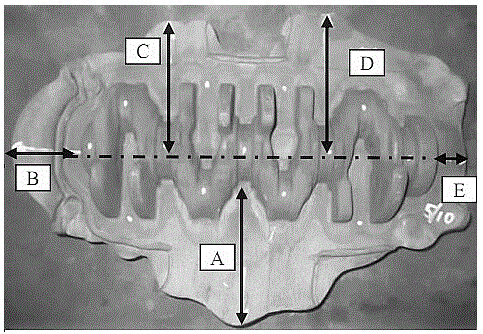
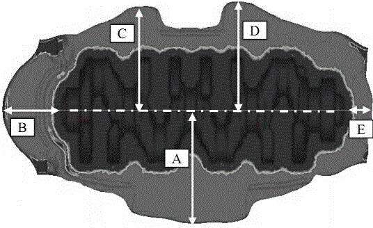
[0041] Step 1, using the orthogonal experiment method, extracting the fillet of the parting surface of the pre-forging die cavity, the length, width and height ratio factors of the pre-forging die cavity and the final forging die cavity, forming four factors, and then establishing the factor level table, specifically As shown in Table 1:

[0042] Table I

[0043]

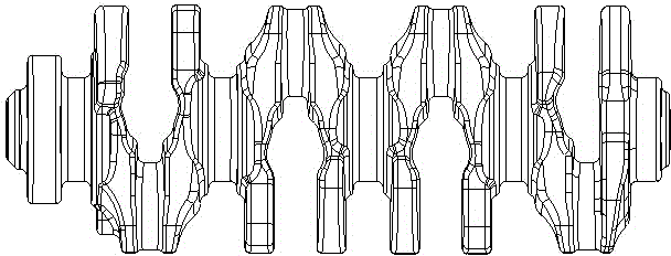
[0044] Step 2, according to the factor level table, draw such as figure 1 The crankshaft model shown;

[0045] Step 3, according to the crankshaft model samples of 16 groups of orthogonal schemes, proceed as follows f...


PUM


Abstract

The invention belongs to the technical field of metal plastic forming processes, and provides a method for conducting analog simulation on the crank die forging process through computer aided engineering (CAE). The method includes the steps of extracting the parting surface chamfer of a pre-forging die chamber, the length ratio factor of the pre-forging die chamber and a final-forging die chamber, the width ratio factor of the pre-forging die chamber and a final-forging die chamber and the height ratio factor of the pre-forging die chamber and a final-forging die chamber through orthogonal experiments, and establishing a factor level table; forging a CAE sample and an actual crank by drawing a crank model through CAD; conducting final-forging load testing, wherein the maximum forming load of the pre-forging die chamber is achieved when the partial surface chamfer is 8, the length ratio is 0.998, the width ratio is 0.98 and the height ratio is 1.12, and the maximum final forging forming load is achieved when the partial surface chamfer is 8, the length ratio is 0.998, the width ratio is 0.95 and the height ratio is 1.09. The finite element principle analysis method which has quite high representativeness, practicability and scientificity has the advantages that workloads are reduced, implementation is easy, the optimal conclusion is obtained, the forming load is greatly reduced, the forming defects are eliminated, and the die service life is prolonged.

Description

technical field [0001] The invention belongs to the technical field of metal plastic forming technology, in particular to a method for computer-aided engineering CAE simulation crankshaft die forging technology. Background technique [0002] As the key component of the engine, the crankshaft is called the heart of the engine. During the operation of the crankshaft, it needs to bear the alternating stress of the load all the time. In order to ensure the normal driving of the car, the crankshaft needs to have excellent impact resistance, toughness, wear resistance and fatigue resistance. Therefore, in order to make the performance of the crankshaft meet the standards when it is running, there are strict specifications for the material selection, forming process, and dynamic balance of the crankshaft. [0003] As a typical complex die forging, the crankshaft is prone to defects such as folding, filling and cracks during the forging process. Nowadays, stable power, fuel econom...

Claims


Application Information

Patent Timeline
Patent Type & Authority Applications(China)
IPC IPC(8): G06F17/50
Inventor 王波
Owner SHANGHAI AIYI INFORMATION TECH
Why Eureka
Try Eureka