
Damping component, crystal oscillation device, frequency synthesizer and electronic device

A technology of frequency synthesizer and crystal oscillation, which is applied in the direction of mechanical equipment, spring/shock absorber, vibration suppression adjustment, etc., can solve the problems of poor durability, vibration reduction effect not meeting the demand, failure, etc., to avoid coupling vibration Effect

Active Publication Date: 2015-05-20
UNIV OF SHANGHAI FOR SCI & TECH
View PDF11 Cites 13 Cited by
  • Summary
  • Abstract
  • Description
  • Claims
  • Application Information

AI Technical Summary

Problems solved by technology

[0004] In order to reduce the vibration impact of the crystal oscillator, in the prior art, the steel wire rope damping device is often used to damp the crystal oscillator. However, the steel wire rope damping device can only have a vibration damping effect in a single direction, although in general It can meet the requirements of electronic information equipment, but for electronic equipment that requires high signal stability and relatively severe vibration in the external environment, the vibration reduction effect of the wire rope damping device is obviously not up to the demand, and after long-term use, The wire rope is prone to breakage and failure, and its durability is poor

Method used


Image

  • Damping component, crystal oscillation device, frequency synthesizer and electronic device
  • Damping component, crystal oscillation device, frequency synthesizer and electronic device
  • Damping component, crystal oscillation device, frequency synthesizer and electronic device

Examples


Embodiment 1

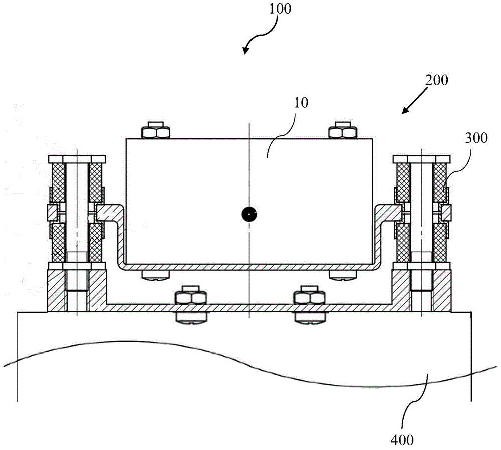
[0035] figure 1 is a schematic structural diagram of the electronic device of this embodiment.

[0036] like figure 1 As shown, the electronic device 100 includes a body 400 and a crystal oscillator 200 fixedly installed thereon. The crystal oscillation device 200 includes a crystal oscillation element 10 and a vibration-damping member 300 that fixes the crystal oscillation element 10 and is used to reduce the interference of external vibrations to the crystal oscillation element. The crystal oscillation element 20 and the vibration-damping member 300 are matched with bolts and studs way to connect. The vibration-damping member 300 and the body 400 are also connected by bolts and studs to indirectly fix the crystal oscillator 20 in the electronic device.

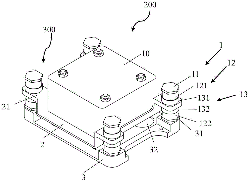
[0037] figure 2 is a schematic diagram of the three-dimensional structure of the crystal oscillation device of this embodiment.

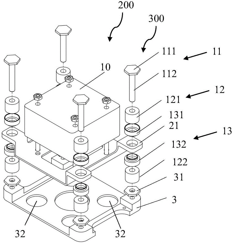
[0038] image 3 It is an exploded view of the three-dimensional structure of the crysta...

Embodiment 2

[0068] In the second embodiment, the same structures as those in the first embodiment are given the same symbols, and the same descriptions are omitted.

[0069] Figure 8 is a schematic diagram of the three-dimensional structure of the crystal oscillation device in this embodiment.

[0070] Figure 9 is an exploded view of the three-dimensional structure of the crystal oscillator in this embodiment.

[0071] Figure 10 It is a schematic diagram of the internal structure of the crystal oscillation device in this embodiment.

[0072] like Figure 8 to Figure 10 As shown, the crystal oscillation device 500 includes a crystal oscillation damping device 600 and a crystal oscillation element 10 fixed thereon. The vibration damping member 400 includes a vibration damping assembly 4 , a support assembly 5 and a base 3 . The damping member 4 includes a pressure member 11 , a metal rubber 41 and a locking piece 31 . The metal rubber 41 is cylindrical and divided into two parts, m...


PUM


Abstract

The invention relates to a metal rubber crystal oscillator damping device. A crystal oscillator is mounted on a bracket; four connecting screw rods with adjustable rigidity and damping are connected with a bottom plate at four corners of the bracket; each connecting screw rod with the adjustable rigidity and damping consists of an adjusting guide pillar, cylindrical metal rubber, a rigid sleeve and a locking sheet, wherein the adjusting guide pillar penetrates through the cylindrical metal rubber, the rigid sleeve and the bracket and is in threaded connection with the locking sheet; a groove is formed in the middle of the bracket; the crystal oscillator is placed in the groove; bosses are arranged on the four corners and are fixedly connected with the rigid sleeves; the cylindrical metal rubber parts are embedded into the rigid sleeves. The device has the advantages that the structure is simple and portable, the installation is convenient, the rigidity and the damping are adjustable, three-dimensional vibration damping performance is excellent, the endurance performance is good, the high temperature resistance, the low temperature resistance and the corrosion resistance are realized, the aging cannot be easily caused, and the like; the practicability is stronger, and the application prospects are wide.

Description

technical field [0001] The invention belongs to the field of vibration reduction, and in particular relates to a vibration reduction component, a crystal oscillator, a frequency synthesizer and electronic equipment. Background technique [0002] Crystal oscillator is the core component of electronic equipment, which can generate the reference oscillation frequency as the reference signal of the electronic equipment. When the electronic equipment needs to use multiple signals, a frequency synthesizer can be used to add, subtract, multiply, and Divide by four arithmetic operations to obtain a series of frequency signals with a certain degree of stability and precision. [0003] In actual work, the vibration of the carrier of the electronic equipment and the vibration caused by the internal components of the electronic equipment will be transmitted to the crystal oscillator, thereby reducing the stability of the oscillation frequency generated by the crystal oscillator, causing...

Claims


Application Information

Patent Timeline
IPC IPC(8): F16F15/08F16F15/06
CPCF16F15/085
Inventor 余慧杰王亚苏颜昕谭云东
Owner UNIV OF SHANGHAI FOR SCI & TECH
Learn More