
Cyclone component of natural gas dry type dedusting separator

A dry dust removal and separator technology, which is applied in the direction of devices, gas fuels, swirling devices, etc.

Inactive Publication Date: 2015-05-20
NINGXIA ZHONGYUAN TIANSHENG TECH
View PDF9 Cites 0 Cited by
  • Summary
  • Abstract
  • Description
  • Claims
  • Application Information

AI Technical Summary

Problems solved by technology

This dust removal method is not suitable for remote and outdoor places without air compressors, such as long-distance natural gas pipeline stations, gas distribution stations, etc.

Method used


Image

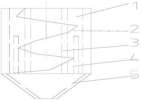
  • Cyclone component of natural gas dry type dedusting separator

Examples


Embodiment 1

[0011] Embodiment 1 Composition of a cyclone subassembly of a natural gas dry-type dedusting separator and the functions of each component:

[0012] A cyclone subassembly of a natural gas dry-type dedusting separator, which consists of an ascending air pipe (1), a spiral guide vane (2), an inner pipe (3), an outer pipe (4), and a cone (5), and is characterized in that The ascending air pipe (1) is installed at the end of the inner pipe (3), and the outer circle of the spiral guide vane (2) has an outer helix angle of 45°-48°. The inner tube (3) is installed in the outer tube (4). The spiral guide vane (2) is welded between the inner tube (3) and the outer tube (4).

Embodiment 2

[0013] Embodiment 2 A kind of working process of the dry type dedusting cylinder of natural gas:

[0014] The gas inner pipe enters from the mouth of the ascending air pipe (1), rotates along the spiral guide vane (2) and the inner pipe (3), the gas rises from the ascending air pipe (1), and the dust is drawn to the cone (5) by centrifugal force for separation .


PUM


Abstract

The invention discloses a cyclone component of a natural gas dry type dedusting separator. The cyclone componentconsists of an ascending gas pipe (1), spiral guide blades (2), an inner pipe (3), an outer pipe (4) and a cone body (5). The cyclone component is characterized in that the ascending gas pipe (1) is installed on the end part of the inner pipe (3); the excircle parts of the spiral guide blades (2) are provided with outer spiral angles of 45 degrees-48 degrees; the outer pipe (4) is internally provided with the inner pipe (3). The cyclone component has the beneficial effects that the outer spiral angles enable the filtering and separation effect of gas and dust of natural gas to be optimal.

Description

technical field [0001] The invention relates to a cyclone subassembly of a natural gas dry-type dedusting separator, which belongs to the technical field of environmental protection equipment. Background technique [0002] At present, the dust removal technology of domestic natural gas mostly adopts pulse bag filter, which needs supporting compressed air control pulse valve. This dust removal method is not suitable for remote and outdoor places without air compressors, such as long-distance natural gas pipeline stations and gas distribution stations. Contents of the invention [0003] The object of the present invention is to overcome the shortcomings of the above technologies, and to provide a cyclone subassembly of a dry dust separator that does not need compressed air as the power of the pulse valve. In order to achieve the purpose of the above invention, it is achieved through the following technical solutions: a cyclone subassembly of a natural gas dry dust separat...

Claims


Application Information

Patent Timeline
Patent Type & Authority Applications(China)
IPC IPC(8): B04C5/107C10L3/10
Inventor 胡江海
Owner NINGXIA ZHONGYUAN TIANSHENG TECH
Learn More