
A reducer for a cutting device of a bolter mining unit

A technology of bolting unit and reducer, which is applied in the direction of transmission parts, mechanical equipment, components with teeth, etc.

Active Publication Date: 2017-12-08
TAIYUAN INST OF CHINA COAL TECH & ENG GROUP +1
View PDF5 Cites 0 Cited by
  • Summary
  • Abstract
  • Description
  • Claims
  • Application Information

AI Technical Summary

Problems solved by technology

[0004] The purpose of the present invention is to solve the problem of insufficient cutting reducer in the existing cutting device, and to provide a reducer for the cutting device of the bolter mining unit

Method used


Image

  • A reducer for a cutting device of a bolter mining unit
  • A reducer for a cutting device of a bolter mining unit
  • A reducer for a cutting device of a bolter mining unit

Examples


Embodiment Construction

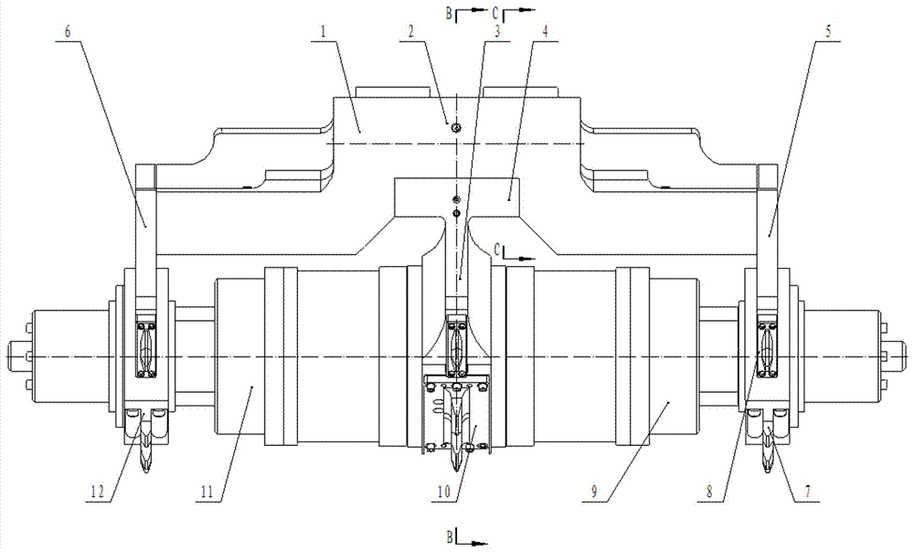
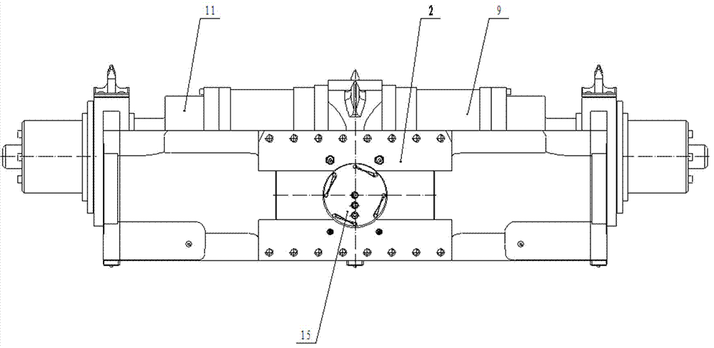
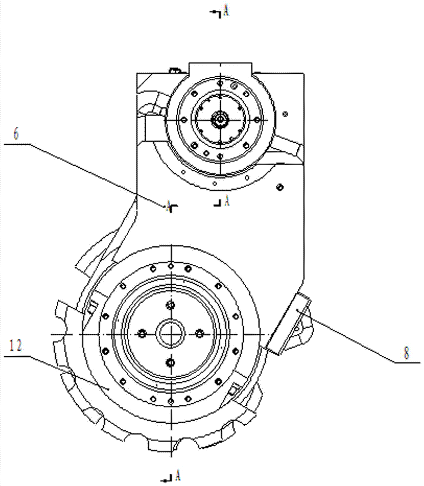
[0023] The present invention will be further described below in conjunction with accompanying drawing: as figure 1 , 2 , 3 shows a reducer for a cutting device of a bolter mining unit, the structure of which includes an upper housing 1, a lower housing 3, a left supporting housing 5, a right supporting housing 6, an upper gear box 2, and a lower gear box 4. Left planetary gearbox 9, right planetary gearbox 11, cutting block 8 and cutting gland 10, left supporting shell gland 7, right supporting shell gland 12, five-stage left planet carrier 32, five-stage Right planet carrier 60, wheel hubs 35, 62; upper casing 1 is provided with upper gear box 2, the two sides of upper gear box 2 are respectively connected with left power input bevel gear shaft 17, right power input bevel gear shaft 16, left power input bevel gear shaft The shaft 17 and the right power input bevel gear shaft 16 are connected to the spline shaft 19 through the driven bevel gear 18, and the spline shaft 19 is ...


PUM


Abstract

The invention relates to a diggingbolt group cutting device, in particular to a speed reducer of the diggingbolt group cutting device to solve the problems of the defects of a cutting speed reducer in an existing cutting device. The speed reducer structurally comprises an upper shell, a lower shell, a left supporting shell, a right supporting shell, an upper gear case, a lower gear case, a left planetary gear case, a right planetary gear case, cutting blocks, a cutting gland, a left supporting shell gland, a right supporting shell gland, a five-level left planet carrier, a five-level right planet carrier and hubs. A left power input bevel gear shaft and a right power input bevel gear shaft are connected with the left planetary gear case and the right planetary gear case through a driven bevel gear, a spline shaft drive helical gear and a transmission shaft respectively. Cutting rollers are connected to the two sides of the left planetary gear case and the right planetary gear case to form double-motor drive, an overall-width cutting mechanism of a diggingbolt group is more stable and reliable in work, the technical support is provided for mining machine serialization development in China, the technical reserve is provided for heavy tunneling devices, and the technological level of the coal mine tunnel tunneling device field in China is improved.

Description

technical field [0001] The invention relates to a cutting device of a bolter digging unit, in particular to a speed reducer of the cutting device of a bolter digging unit. Background technique [0002] In coal mine underground mining equipment, the bolter digging unit relies on the full-width cutting device to realize the tunneling and forming at one time. The cutting device is the most important core working part of the whole machine. Driven by a motor, the cutting width is large, up to 5-6m, the cutting capacity is strong, and the production efficiency is high. It has many advantages over the longitudinal axis cutting device and the short horizontal axis cutting device. [0003] The cutting device of the bolter mining unit mainly includes a cutting reducer, a telescopic drum, and a cutting motor. When the bolter unit is working, the cutting device moves to the designated position, the cutting motor is started, and the cutting drum is extended to the width of the roadway t...

Claims


Application Information

Patent Timeline
Patent Type & Authority Patents(China)
IPC IPC(8): F16H57/02F16H57/04F16H57/08F16H57/038
CPCF16H57/02F16H57/038F16H57/04F16H57/0436F16H57/08
Inventor 张小峰高爱红曹为李亭洁宋庭锋杨敬伟马福文杨勤车利明戴志晔张维果陈庆贺李发泉马凯梁大海马强崔炎霞张强
Owner TAIYUAN INST OF CHINA COAL TECH & ENG GROUP
Learn More