
Explosive segmental detonation cracking method at the root of the surface annular groove during pipe blanking

An annular groove and pipe technology, which is applied in the field of segmental detonation and initiation of explosives at the root of the annular groove on the surface of the pipe during cutting, can solve the problems of long cutting time, low processing efficiency, collapse of the pipe wall, etc., and save the amount of medicine. , The effect of shortening the blanking cycle and improving the blanking efficiency

Active Publication Date: 2016-06-29
XI AN JIAOTONG UNIV
View PDF4 Cites 0 Cited by
  • Summary
  • Abstract
  • Description
  • Claims
  • Application Information

AI Technical Summary

Problems solved by technology

Traditional pipe blanking mainly adopts cutting, stamping processing or thermal cutting, etc., which often have problems such as high energy consumption, low processing efficiency, poor section quality, or pipe wall collapse and pipe deformation.
In recent years, precision blanking technologies such as prefabricated gaps using stress concentration effects and high-frequency low-stress circumferential swaging blanking have made pipe blanking develop in the direction of green manufacturing with low energy consumption, high quality, high productivity, and low pollution. The material time is long, which cannot meet the requirements of mass production
There are no reports on the combination of explosive detonation and pipe cutting

Method used


Image

  • Explosive segmental detonation cracking method at the root of the surface annular groove during pipe blanking
  • Explosive segmental detonation cracking method at the root of the surface annular groove during pipe blanking
  • Explosive segmental detonation cracking method at the root of the surface annular groove during pipe blanking

Examples


Embodiment Construction

[0022] The present invention will be described in further detail below in conjunction with the accompanying drawings.

[0023] The method for detonating and cracking the root of the annular groove on the surface of the explosive by segmental detonation during the blanking of the pipe comprises the following steps:

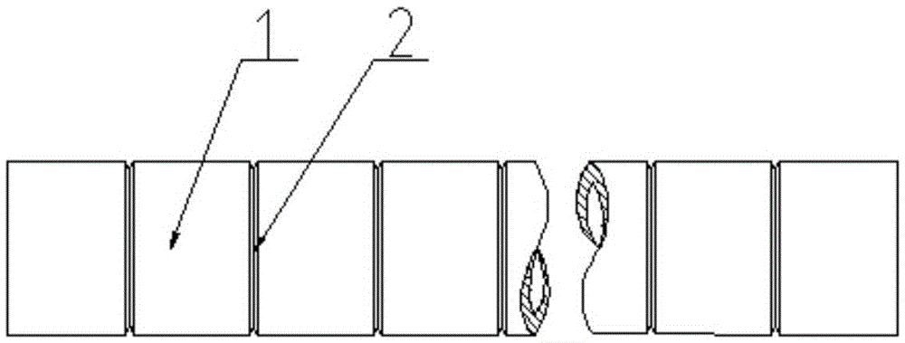
[0024] Step 1. Before cracking, the outer surface of the long pipe 1 is cut into an annular V-groove 2 according to the cutting length of each section, such as figure 1 shown;

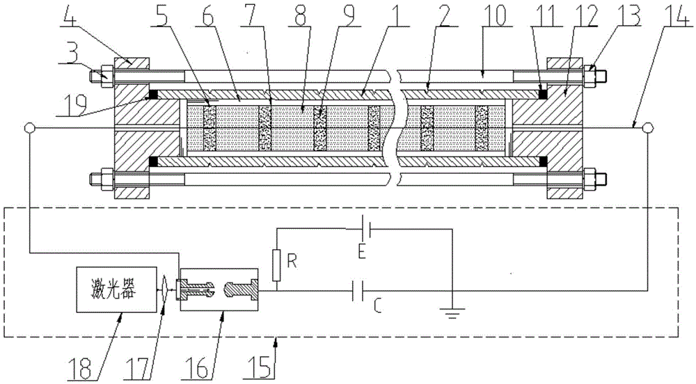
[0025] Step 2. When assembling, fill the long pipe 1 with a long detonation tube 5 of equal diameter, make the powder column 9 correspond to the root section of the annular V groove 2, and seal the first flange head 4 and the second flange The head 12 is installed and clamped at both ends of the long pipe 1, and the first flange head 4 and the second flange head 12 are tensioned axially with the first bolt 10;

[0026] Step 3. When cracking, turn on the laser 18, trigger the ball gap high...


PUM

PropertyMeasurementUnit
densityaaaaaaaaaa
diameteraaaaaaaaaa
diameteraaaaaaaaaa

Abstract

A segmented explosive detonation and crack initiation method used on the root portion of a surface annular groove during tube blanking includes the steps that the annular V groove is formed in the outer surface of a long tube according to the blanking length, a cavity is filled with a long detonation cylinder with the diameter same as the annular V groove, a grain is enabled to correspond to the root portion of the annular V groove in a segment-to-segment mode, a first flange end socket and a second flange end socket are clamped to the two ends of the long tube and are tightly tensioned in the axial direction through first bolts, a high-pressure sphere gap switch is triggered by a laser device to be switched on during crack initiation, large pulse current is applied to a copper wire coaxial with the grain, the grain is detonated segment by segment to generate transient high-energy high-pressure shock waves, the inner wall of the long tube is loaded segment by segment, the root portion of the annular V groove is made to plastically deform due to stress concentration, and micro crack groups are generated. According to the method, non-coupling spaced loading is adopted, explosive quantity is effectively reduced, and the method has the advantages of shortening the blanking period, improving blanking efficiency and the like.

Description

technical field [0001] The invention belongs to the technical field of pipe blanking, and in particular relates to a method for explosive detonation initiation and cracking at the root of an annular groove on the surface during pipe blanking. Background technique [0002] The blanking of metal pipes widely exists in the preparation process of conveyor chain roller sleeves, inner (outer) rings of rolling bearings, sliding bearing bushes, etc. The quantity of blanking is huge, and the quality of the blanking directly affects the manufacturing accuracy and production of parts. efficiency and economic cost. Traditional pipe blanking mainly adopts cutting, stamping processing or thermal cutting, etc., which often have problems such as high energy consumption, low processing efficiency, poor section quality, or pipe wall collapse and pipe deformation. In recent years, precision blanking technologies such as prefabricated gaps using stress concentration effects and high-frequency ...

Claims


Application Information

Patent Timeline
Patent Type & Authority Patents(China)
IPC IPC(8): B21D26/08
Inventor 赵升吨董渊哲张超孟德安
Owner XI AN JIAOTONG UNIV
Learn More