Anti-displacement esophageal stent apparatus bag
A technology for esophagus and instruments, which is applied in the field of anti-displacement esophageal stent instrument package, which can solve the problems of increased treatment costs and achieve the effects of reducing discomfort and avoiding complications
- Summary
- Abstract
- Description
- Claims
- Application Information
AI Technical Summary
Problems solved by technology
Method used
Image
Examples
Embodiment 1
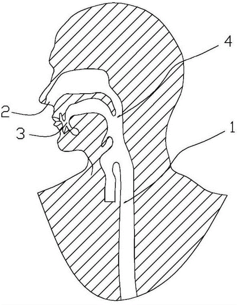
[0040] See attached Figure 2-6 , an anti-displacement esophageal stent kit comprising: an esophageal stent 5; a conveyor 6; a buffer fixing tube 7; a threader 8;
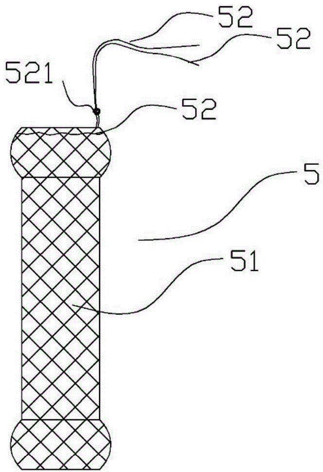
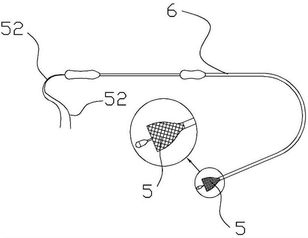
[0041] from figure 2 It can be seen from the figure that the esophageal stent 5 includes a stent body 51 and a fixed wire 52, and the fixed wire 52 circles around the upper mouth of the stent body 51 to tie a fixed knot 521; image 3 It can be seen from the figure that the esophageal stent 5 is loaded in the distal end of the conveyor 6, and the fixing wire 52 extends from the proximal end of the conveyor 6; Figure 4 It can be seen from the above that there is a concave hole 71 in the middle of the buffer fixing pipe 7 in the first embodiment; Figure 5 , Image 6 It can be seen from the figure that the threader 8 is composed of a sheath tube 81 and a ferrule 82, and the ferrule 82 passes through the inner cavity of the sheath tube 81; The structure of the stent body 51 of the present invention is mesh or hel...
Embodiment 2
[0057] See attached figure 2 ,3 , 5, 10, 11, an anti-displacement esophageal stent device kit includes: esophageal stent 5; conveyor 6; threader 8; buffer fixing tube 9.
[0058] See attached Figure 10 , it can be known that the buffer fixing tube 9 in the second embodiment has two through holes 91; the buffer fixing tube 9 is a conical frustum.
[0059] See attached Figure 11 Figures (a) and (b) in the middle are schematic diagrams of external fixation of the fixed line in Example 2, and the specific process is as follows:
[0060] 1) Pass the two fixing lines 52 through the two through holes 91 on the bottom surface of the buffer fixing tube 9 respectively, and pass through the through holes 91 on the bottom surface of the buffer fixing tube 9;
[0061] 2) Push the buffer fixing tube 9 into the nostril 2 on one side along the fixing line;
[0062] 3) Properly tighten the two fixing lines 52, then tie the two fixing lines 52 and fix them, and trim the length of the thr...
Embodiment 3
[0065] see Figure 12 , two slender hoses 10 are bonded to the head end of the buffer fixing tube 7, the through hole of the hose 10 communicates with the through hole 71, and the two fixing lines 52 penetrate through the end of the through hole of the hose 10 respectively, and connect from the head end of the 71 Pass it out, and then fix the two fixing lines 52 with knots. The length of the hose 10 exceeds the pharynx 4 . Refer to Embodiment 1 for the rest of the process, which will not be repeated here.
PUM
 Abstract
Description
Claims
Application Information
 - R&D Engineer
- R&D Manager
- IP Professional
- Industry Leading Data Capabilities
- Powerful AI technology
- Patent DNA Extraction
Browse by: Latest US Patents, China's latest patents, Technical Efficacy Thesaurus, Application Domain, Technology Topic, Popular Technical Reports.
© 2024 PatSnap. All rights reserved.Legal|Privacy policy|Modern Slavery Act Transparency Statement|Sitemap|About US| Contact US: help@patsnap.com


