
Intelligent radar based on target motion matching

A technology of motion matching and radar, which is applied in the direction of radio wave reflection/re-radiation, using re-radiation, measuring devices, etc., can solve the problem that it is difficult to meet the requirements of centimeter-level distance measurement, accurate matched filter can not be used in radar systems, and affects target detection and estimation accuracy, to achieve general convenience in programming and development, improve signal detection performance and parameter estimation accuracy, and have strong high-speed parallel processing capabilities

Active Publication Date: 2015-05-06
NO 63921 UNIT OF PLA
View PDF4 Cites 14 Cited by
  • Summary
  • Abstract
  • Description
  • Claims
  • Application Information

AI Technical Summary

Problems solved by technology

Therefore, the movement of the target will cause a mismatch between the echo signal and the receiver filter, resulting in a loss of signal-to-noise ratio and affecting the accuracy of target detection and estimation
At present, in the radar system, pre-distortion of the transmitted waveform or compensation of the echo signal are generally used to reduce the mismatch. However, to design a filter that strictly matches the echo signal, it is necessary to accurately perceive the motion state of the target and establish The mapping relationship between target motion parameters and reflected signal waveform parameters involves complex mathematical modeling and calculations. Therefore, accurate matched filtering based on target motion has not been truly realized in radar systems for a long time.
With the increase in the application requirements of radar in the field of high-precision measurement, it is difficult for the pulse measurement radar of this traditional scheme to meet the measurement requirements of centimeter-level ranging and speed measurement accuracy, especially for the matching and high-precision measurement of high-dynamic targets.

Method used


Image

  • Intelligent radar based on target motion matching
  • Intelligent radar based on target motion matching
  • Intelligent radar based on target motion matching

Examples


Embodiment Construction

[0023]In order to further explain the technical means and effects that the present invention takes to achieve the intended purpose of the invention, the specific implementation methods, steps, and structure of the intelligent radar based on target motion matching proposed according to the present invention will be described below in conjunction with the accompanying drawings and preferred embodiments. , features and their effects in detail.

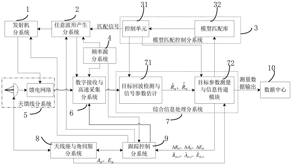
[0024] see figure 1 As shown, it is a schematic diagram of the principle of the smart radar based on target motion matching in the present invention. The intelligent radar based on target motion matching of the present invention preferably includes a transmitter subsystem 1, an arbitrary waveform generation subsystem 2, a model matching control subsystem 3, a frequency source subsystem 4, an antenna feeder subsystem 5, and a digital receiving and high-speed acquisition subsystem. System 6, integrated information processing subsystem 7, a...


PUM


Abstract

The invention relates to an intelligent radar based on target motion matching. The intelligent radar based on target motion matching is characterized by comprising a transmitter subsystem, a random waveform producing subsystem, a model matching control subsystem, a frequency source subsystem, an antenna feeder subsystem, a digital receiving and high-speed acquisition subsystem, an integrated information processing subsystem, an antenna pedestal and angle servo subsystem and a tracking control subsystem. The intelligent radar has the advantages of being high in intelligence, digital and high in accuracy, having openness and the like.

Description

technical field [0001] The invention relates to the field of radar measurement, in particular to an intelligent radar based on target motion matching. Background technique [0002] The ground-based pulse measurement radar is the main equipment for aerospace measurement and control and equipment testing. The basic components of the system include antenna feeder, antenna base and angle servo, transmitter, receiver, frequency source, signal processing, distance measurement and speed measurement subsystem, which can realize the aircraft The continuous reading tracking of the target and its spatial position include the measurement of distance, azimuth, pitch angle and radial velocity. The radar transmitter receives the excitation waveform signal and timing signal from the frequency source subsystem, generates high-power electromagnetic waves, and radiates to space through the antenna feeder. Down-conversion, filtering, and amplification processing are converted to intermediate f...

Claims


Application Information

Patent Timeline
Patent Type & Authority Applications(China)
IPC IPC(8): G01S13/50G01S13/66
CPCG01S7/282G01S7/285G01S7/2923G01S13/582G01S13/72
Inventor 钱卫平张艳金胜郭军海郭永强
Owner NO 63921 UNIT OF PLA
Learn More