
Device for controlling flow direction of fluid through temperature

A temperature control and fluid technology, applied in the valve operation/release device, valve device, pipeline protection through thermal insulation, etc., can solve the problems of influence, increase the workload of staff, heat loss, etc., to achieve convenient use and reduce walking Distance, the effect of reducing workload

Active Publication Date: 2015-05-06
SUZHOU SICHENGZHE INFORMATION TECH CO LTD
View PDF5 Cites 0 Cited by
  • Summary
  • Abstract
  • Description
  • Claims
  • Application Information

AI Technical Summary

Problems solved by technology

However, there will be a small amount of heat loss during the transportation process, and when the pipeline is transported, the temperature of the pipeline itself will also have a certain impact on the material liquid, which will have a relatively adverse impact on chemical production. The existing treatment method is to The cooled material liquid in the pipe is directly discharged or recycled, and then added to the chemical reaction equipment after the overall temperature of the material liquid is satisfied, so that most of the processes require staff to operate, which greatly increases the workload

Method used


Image

  • Device for controlling flow direction of fluid through temperature

Examples


Embodiment

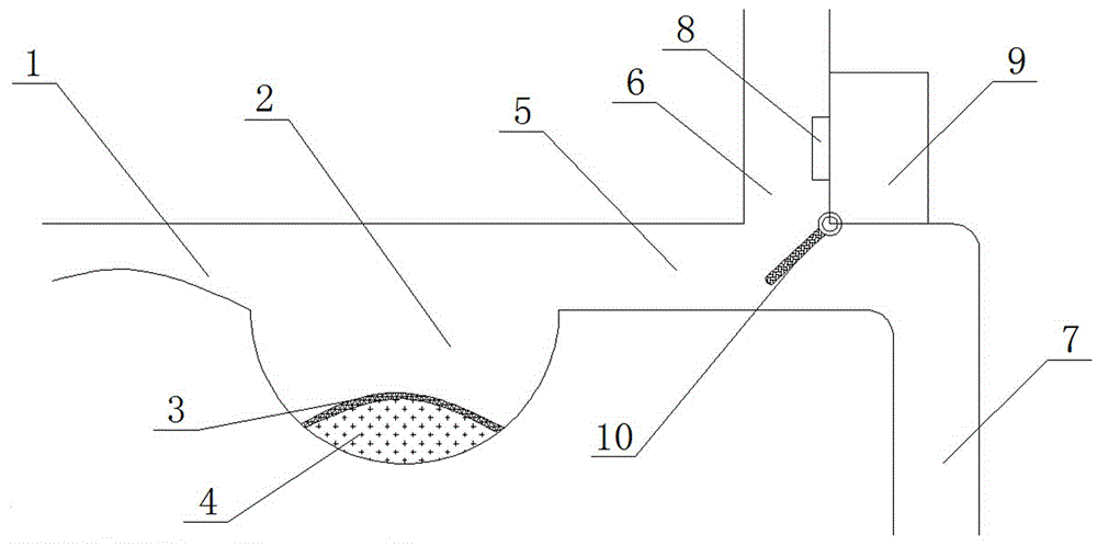
[0026] The main structure of this embodiment, such as figure 1 As shown, including a buffer pipeline and a valve system, the fluid delivery pipe 1 of the buffer pipeline communicates with the fluid inlet pipe 5 of the valve system;

[0027] The fluid delivery tube 1 is included, and the middle part of the fluid delivery tube 1 is sunken to form a mixing chamber 2. An elastic layer 3 is sealed inside the mixing chamber 2. The elastic layer 3 and the inner wall of the mixing chamber 2 form an expansion bag. Filled with expansion medium4. A concave mixing chamber 2 is added in the fluid delivery pipe, so that when the cold fluid in the pipe flows through the fluid delivery pipe 1, it enters the mixing chamber 2 first, and then the hot fluid enters the mixing chamber 2 to mix with the cold fluid, so that the overall temperature of the fluid Elevation; the mixing chamber 2 is also sealed with an elastic layer 3, and the inside of the elastic layer 3 is filled with an expansion med...


PUM


Abstract

The invention discloses a device for controlling the flow direction of fluid through temperature. The device comprises a buffer pipeline and a valve system, wherein a fluid delivery pipe of the buffer pipeline is communicated with a fluid inlet pipe of the valve system; the buffer pipeline comprises the fluid delivery pipe; the middle part of the fluid delivery pipe is downwards sunken to form a mixing cavity in which an elastic layer is sealed; the elastic layer and the inner wall of the mixing cavity form an expansion bag in which an expansion medium is filled; the valve system comprises the fluid inlet pipe, an upper fluid outlet pipe and a lower fluid outlet pipe; the lower part of the fluid inlet pipe is directly communicated with the lower fluid outlet pipe, and the upper fluid outlet pipe is connected to the middle part of the fluid inlet pipe; a temperature probe is arranged on the inner wall of the upper fluid outlet pipe, and is connected with an external control system for controlling a two-way stop valve at the upper fluid outlet pipe and the fluid inlet pipe. According to the device, the buffer pipeline and the valve system are additionally arranged, so that the fluid can be completely ensured to be at optimal material fluid temperature when entering chemical reaction equipment for reaction, and the reaction efficiency of the material fluid is greatly improved.

Description

technical field [0001] The invention relates to the field of chemical fluid delivery equipment, in particular to a device for controlling fluid flow through temperature. Background technique [0002] In the work of chemical plants, the transportation of fluid materials is an indispensable part. Some chemical materials that need to be added need to have a suitable temperature to maintain good production efficiency when they are put into reaction equipment such as reactors. The existing method for keeping the temperature of the fluid material liquid constant is to coat the outer layer of the pipeline with an insulating layer so that the fluid does not lose heat during the flow process, thereby ensuring a constant temperature of the fluid material liquid. However, there will be a small amount of heat loss during the transportation process, and when the pipeline is transported, the temperature of the pipeline itself will also have a certain impact on the material liquid, which w...

Claims


Application Information

Patent Timeline
IPC IPC(8): F16K11/052F16K31/64F16L53/00F16L59/14
CPCF16K11/052F16K31/002F16L53/00F16L59/14
Inventor 周洁
Owner SUZHOU SICHENGZHE INFORMATION TECH CO LTD
Learn More