Air pressure large force suction cup

A suction cup and air pressure technology, applied in the field of parts clamping, can solve the problems of unfavorable use of workpieces, easy magnetization of workpieces, high labor intensity, etc., and achieve the effects of reducing labor intensity, uniform pressing force, and convenient clamping.

Inactive Publication Date: 2015-05-06
SHAANXI TIANYUAN MATERIALS PROTECTION TECH
View PDF0 Cites 1 Cited by
  • Summary
  • Abstract
  • Description
  • Claims
  • Application Information

AI Technical Summary

Problems solved by technology

However, when processing thin plates or workpieces with soft materials, if combined fixtures are used, the workpieces are easily deformed and labor-intensive; when processing workpieces with good magnetic permeability, if electromagnetic chucks are used, the workpieces are easily magnetized. Some occasions that are sensitive to magnetism are not conducive to the use of the workpiece, and if the workpiece is a non-magnetic material, there is nothing to do

Method used


Image

  • Air pressure large force suction cup
  • Air pressure large force suction cup
  • Air pressure large force suction cup

Examples


Embodiment Construction

[0016] The present invention will be described in further detail below in conjunction with the accompanying drawings and specific embodiments.

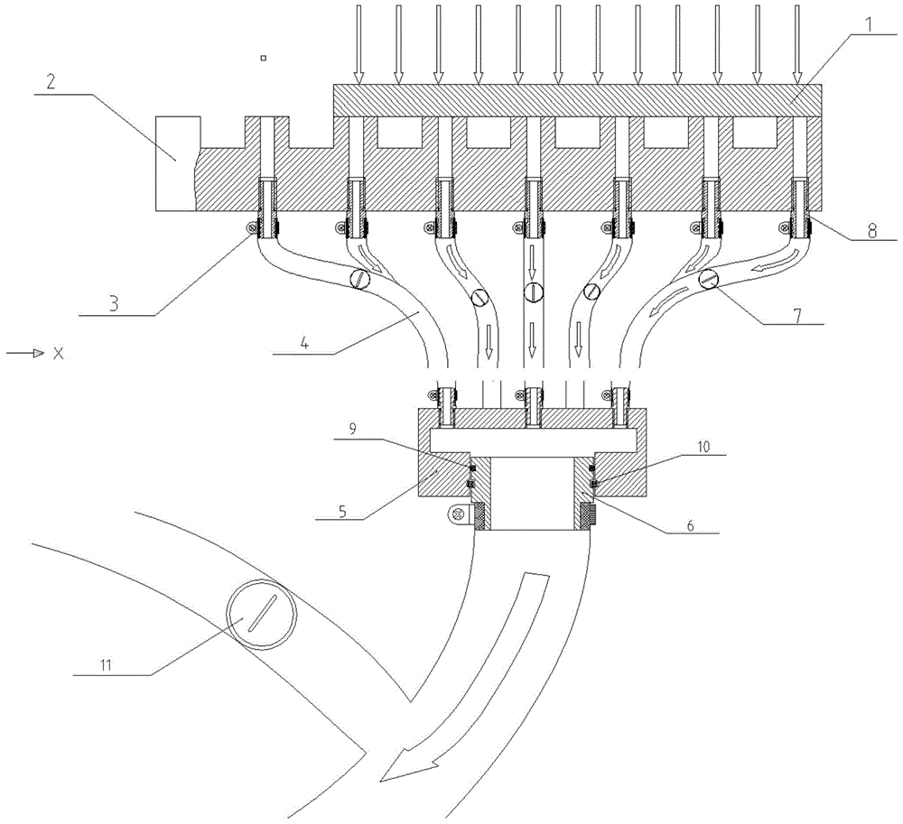
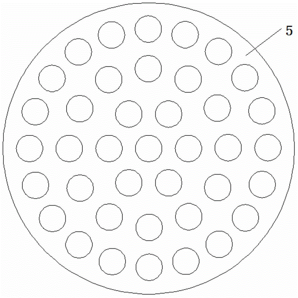
[0017] Such as figure 1 As shown, a pneumatic suction cup of the present invention includes a clamping platform 2, on which a plurality of identical square platforms are milled, each platform is punched with a through hole, and the bottom of the through hole is threaded , a plurality of high-pressure air pipes 4 are connected to the through-holes through the air pipe joints 8 inserted into the bottom of the through-holes. The high-pressure air pipes 4 are equipped with air valves 7 and also include round cake joints 5. The round cake joints 5 are round cake-shaped cavity structures, on which The surface is evenly distributed with multiple identical screw holes, and the other ends of multiple high-pressure air pipes 4 are connected to the round cake joint 5 through the air pipe joint 8 inserted into the screw hole, and the lower openin...


PUM


Abstract

An air pressure large force suction cup comprises a clamping platform, and a plurality of same square tables are milled on the clamping platform; through holes are punched in the square tables, and threads are arranged at the bottoms of the through holes; a plurality of high-pressure air pipes are connected with the through holes through air pipe joints inserted into the bottoms of the through holes; and air valves are arranged on the high-pressure air pipes. A round cake joint is further included, and is of a round cake cavity structure, and a plurality of same screw holes are evenly distributed in the upper surface of the round cake joint; and the other ends of the high-pressure air pipes are connected with the round cake joint through the air pipe joints inserted into the screw holes. An opening in the lower portion of a cavity of the round cake joint is matched with an air pipe chuck through an O-shaped ring, and is limited through a spring clamping strip, and the other end of the air pipe chuck is connected with an air compressor pipe; and a pressure relief valve is arranged on a branch of the air compressor pipe. The air pressure large force suction cup has the advantages of being convenient, easy to operate, efficient and low in cost.

Description

technical field [0001] The invention relates to the technical field of parts clamping such as plates, and in particular to a pneumatic suction cup. Background technique [0002] In the process of clamping parts such as boards, it is customary in the industry to use combined fixtures or electromagnetic chucks. However, when processing thin plates or workpieces with soft materials, if combined fixtures are used, the workpieces are easily deformed and labor-intensive; when processing workpieces with good magnetic permeability, if electromagnetic chucks are used, the workpieces are easily magnetized. Some occasions that are sensitive to magnetism are not conducive to the use of the workpiece, and if the workpiece is a non-magnetic material, there is nothing to do. Contents of the invention [0003] In order to solve the above-mentioned problems in the prior art, the purpose of the present invention is to provide a pneumatic suction cup with the characteristics of convenience,...

Claims


Application Information

Patent Timeline
Patent Type & Authority Applications(China)
IPC IPC(8): B23Q3/00
CPCB23Q3/00B23Q2703/04B23Q2703/10
Inventor 吴兴
Owner SHAANXI TIANYUAN MATERIALS PROTECTION TECH
Why Eureka
Try Eureka