Heat dissipation system for high-frequency high voltage power supply

A high-frequency high-voltage power supply and heat dissipation system technology, which is applied in the direction of transformer/inductor cooling, cooling/ventilation/heating transformation, etc., can solve the problems of polluting electronic components, transformer oil leakage, poor heat dissipation, etc., and achieve energy saving , prevent seepage, reduce the effect of temperature

Inactive Publication Date: 2015-04-29
大连德维电子科技有限公司
View PDF0 Cites 7 Cited by
  • Summary
  • Abstract
  • Description
  • Claims
  • Application Information

AI Technical Summary

Problems solved by technology

[0002] Due to the small size, high integration and high output power of the high-frequency high-voltage power supply, a large amount of heat will be generated during its operation, which needs to be removed in time to ensure the thermal stability of the high-frequency high-voltage power supply. The requirements are high, and a good heat dissipation system can ensure the stable performance of the high-frequency high-voltage power supply and improve the reliability of the high-frequency high-voltage power supply; the existing heat dissipation systems for high-frequency high-voltage power supplies mainly include oil cooling and air cooling. The cooling method dissipates heat from the transformer included in the high-frequency and high-voltage power supply, and it is easy for the transformer oil to seep from the oil pump, thereby contaminating other electronic components in the high-frequency and high-voltage power supply; the cooling effect of the wind cooling method is not good, wasting electric energy

Method used


Image

  • Heat dissipation system for high-frequency high voltage power supply

Examples


Embodiment Construction

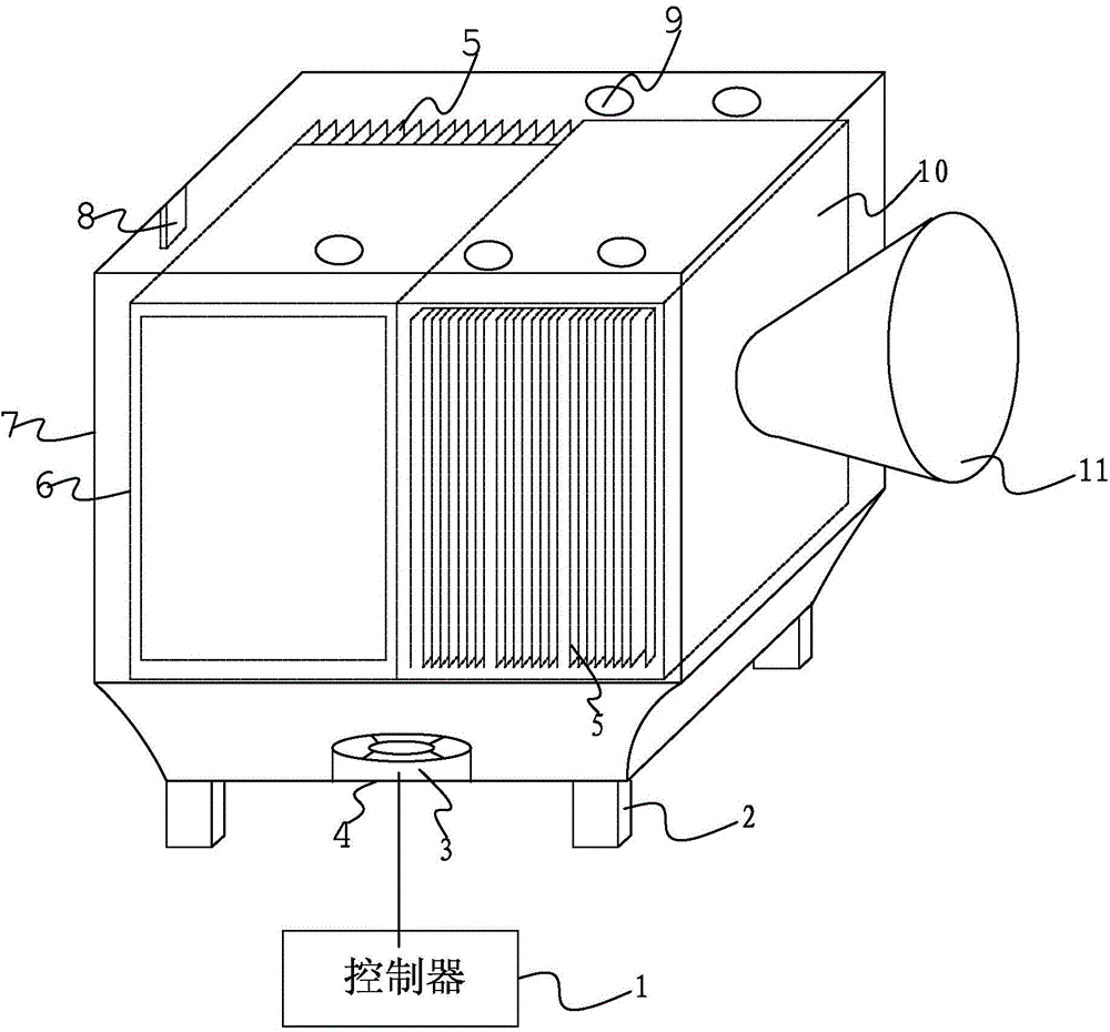
[0019] like figure 1 The heat dissipation system shown for high-frequency high-voltage power supply is applied to high-frequency high-voltage power supply. The high-frequency high-voltage power supply includes a casing, a fuel tank 10 and an inverter box placed in the casing; a high-voltage power supply is placed inside the fuel tank 10 Transformer; characterized in that it includes: a fan 3 installed on the bottom surface of the casing; an air inlet 4 arranged on the bottom surface of the casing corresponding to the position of the fan 3; a radiator 5 installed on the outer wall of the oil tank 10 and the inverter box; Inside the casing, a temperature sensor for monitoring temperature changes inside the casing; a plurality of cooling holes on the top of the casing; a detachable dust-proof net arranged outside the cooling holes; brackets 2 arranged at the four corners of the bottom of the casing; The input module used to receive the start-stop control command of the fan 3 from...


PUM


Abstract

The invention discloses a heat dissipation system for a high-frequency high voltage power supply. The heat dissipation system comprises a fan, an air inlet, a heat dissipater, a temperature sensor, a plurality of heat dissipation holes, detachable dust screens, supports, an input module and a controller, wherein the fan is mounted on the bottom surface in a shell, and the air inlet is formed in the bottom surface of the shell and corresponds to the fan in position; the heat dissipater is mounted on the outer walls of a fuel tank and an inversion tank, and the temperature sensor is mounted in the shell and used for monitoring the temperature variation in the shell; the heat dissipation holes are formed in the top of the shell, and the dust screens are arranged outside the heat dissipation holes; the supports are arranged at the four corners of the bottom of the shell, and the input module is used for receiving the start-stop control instruction of the fan; the controller is connected with the temperature sensor, the fan and the input module. The heat dissipation system has the advantages of being simple in structure and good in heat dissipation effect.

Description

technical field [0001] The invention relates to a cooling system for a high-frequency high-voltage power supply. Background technique [0002] Due to the small size, high integration and high output power of the high-frequency high-voltage power supply, a large amount of heat will be generated during its operation, which needs to be removed in time to ensure the thermal stability of the high-frequency high-voltage power supply. The requirements are high, and a good heat dissipation system can ensure the stable performance of the high-frequency high-voltage power supply and improve the reliability of the high-frequency high-voltage power supply; the existing heat dissipation systems for high-frequency high-voltage power supplies mainly include oil cooling and air cooling. The cooling method dissipates heat from the transformer included in the high-frequency and high-voltage power supply, which is prone to seepage of transformer oil from the oil pump, which in turn contaminate...

Claims


Application Information

Patent Timeline
Patent Type & Authority Applications(China)
IPC IPC(8): H05K7/20H01F27/08
Inventor 郭知初王霆郭智新姜锋
Owner 大连德维电子科技有限公司
Why Eureka
Try Eureka