
Hydrogen power generation system and power generation method

A power generation system, hydrogen technology, applied in circuits, fuel cells, electrical components, etc., can solve problems such as affecting cooling efficiency, being paralyzed, and unfavorable energy saving, and achieve the effect of reducing noise pollution, wide application fields, and low overall power.

Active Publication Date: 2015-04-29
GUANGDONG HYDROGEN ENERGY SCI & TECH
View PDF6 Cites 16 Cited by
  • Summary
  • Abstract
  • Description
  • Claims
  • Application Information

AI Technical Summary

Problems solved by technology

In the prior art, the fuel cell cooling system mainly includes a water circulation cooling system, and its main components include a heat sink in the fuel cell, a water pump, and related supporting pipelines and supporting water tanks. However, the fuel cell cooling systems in the prior art all use a single The water pump is used as the power to drive the water cycle, and the problems it produces are: First, when a single water pump is used as power, the water pump is often required to have a large power, and the power supply of the water pump often comes from a fuel cell. Therefore, a single water pump When used as power, it needs to consume more energy and occupy more electric energy generated by fuel cells, which is not conducive to energy saving; second, the safety of a single water pump is low. When the water pump fails, the water circulation cooling system is paralyzed, directly damaging Fuel cell; third, a single water pump has high power and high noise; fourth, when the power of a single water pump is not enough, it is difficult to increase the water circulation flow, which affects the cooling efficiency

Method used


Image

  • Hydrogen power generation system and power generation method
  • Hydrogen power generation system and power generation method
  • Hydrogen power generation system and power generation method

Examples


Embodiment Construction

[0038] The structural principle and working principle of the present invention will be further described in detail below in conjunction with the accompanying drawings.

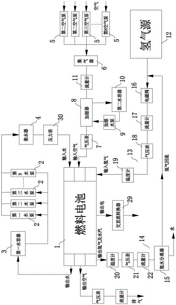
[0039] Such as figure 1 As shown, a hydrogen power generation system includes a fuel cell 1 and a water circulation cooling system, the fuel cell 1 is used for electrochemical reaction of hydrogen and oxygen to generate electric energy, and the water circulation cooling system is used for heat dissipation and cooling of the fuel cell 1; The water circulation cooling system includes a cooling device, at least two water pumps 2, a first water container 3, a water collector 4 and a control device (not shown in the figure); the cooling device is located in the fuel cell 1; the first water container The water in 3 can be driven by the water pump 2, after being collected by the water collector 4, enter the cooling device from the water inlet of the fuel cell 1, and then flow back to the first water container 3 from ...


PUM


Abstract

The invention discloses a hydrogen power generation system and a power generation method. The hydrogen power generation system comprises a fuel cell and a water cycle cooling system, wherein the fuel cell is used for electrochemical reaction between hydrogen and oxygen to generate electric energy and the water cycle cooling system is used for cooling the fuel cell; the water cycle cooling system comprises a cooling device, at least two water pumps, a first water container, a water collector and a control device; the cooling device is arranged in the fuel cell; driven by the water pumps, water in the first water container is collected by the water collector, then enters into the cooling device through a water inlet of the fuel cell and returns to the first water container from a water outlet of the fuel cell; the control device is electrically connected with the at least two water pumps so as to control operations of all the water pumps. The water cycle cooling system of the power generation system is low in energy consumption, low in noise, high in safety, strong in reliability and high in cooling efficiency.

Description

technical field [0001] The invention relates to the technical field of power generation equipment, in particular to a hydrogen power generation system and a power generation method thereof. Background technique [0002] Hydrogen is one of the most ideal energy sources in the 21st century. When burning the same weight of coal, gasoline and hydrogen, hydrogen produces the most energy, and the product of its combustion is water without ash and waste gas. pollute the environment; while coal and oil combustion mainly produce CO 2 and SO 2 , which can produce the greenhouse effect and acid rain respectively. The reserves of coal and oil are limited, while hydrogen is mainly stored in water, and the only product after combustion is water, which can continuously produce hydrogen and never run out. The distribution of hydrogen is very wide, and water is a large "warehouse" of hydrogen, which contains 11% hydrogen. There is about 1.5% hydrogen in soil; oil, coal, natural gas, anim...

Claims


Application Information

Patent Timeline
Patent Type & Authority Applications(China)
IPC IPC(8): H01M8/04H01M8/04029H01M8/04298H01M8/04313
CPCH01M8/04029Y02E60/50
Inventor 向华
Owner GUANGDONG HYDROGEN ENERGY SCI & TECH
Learn More