Radioactive Iodine‑131 Vapor Treatment Unit

A processing device and a technology of radioactive iodine, which are applied in the field of radioactive iodine-131 vapor processing devices, can solve the problems of large effective operation space, large radiation dose for staff, lack of adsorption effect of activated carbon column, etc., and achieve the effect of safe processing

Inactive Publication Date: 2017-03-29
INST OF NUCLEAR PHYSICS & CHEM CHINA ACADEMY OF
View PDF7 Cites 0 Cited by
  • Summary
  • Abstract
  • Description
  • Claims
  • Application Information

AI Technical Summary

Problems solved by technology

[0005] In order to overcome that the radioactive iodine-131 vapor treatment device in the prior art occupies a relatively large effective operating space in the shielding work box, the used plastic tube or latex tube is prone to aging and cracking under long-term high-dose radioactive iodine-131 gamma ray irradiation, and the pipeline It is troublesome to replace the invalid activated carbon, etc., and the staff are exposed to large radiation doses, lack of on-site real-time monitoring of the adsorption effect of the activated carbon column and exhaust emissions, resulting in insufficient emissions of radioactive iodine-131 tail gas exceeding the standard, which can be realized in an effective operating space. The high-efficiency treatment of radioactive iodine-131 vapor in a small shielded work box facilitates the recovery of most (higher than 95%) of iodine-131, and achieves the purpose of controlling the risk of radioactive pollution and meeting the emission standards of tail gas. The present invention provides a Radioactive iodine-131 vapor treatment device

Method used


Image

  • Radioactive Iodine‑131 Vapor Treatment Unit
  • Radioactive Iodine‑131 Vapor Treatment Unit
  • Radioactive Iodine‑131 Vapor Treatment Unit

Examples


Embodiment 1

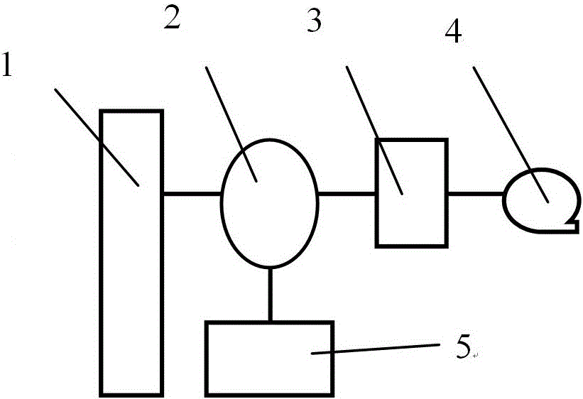
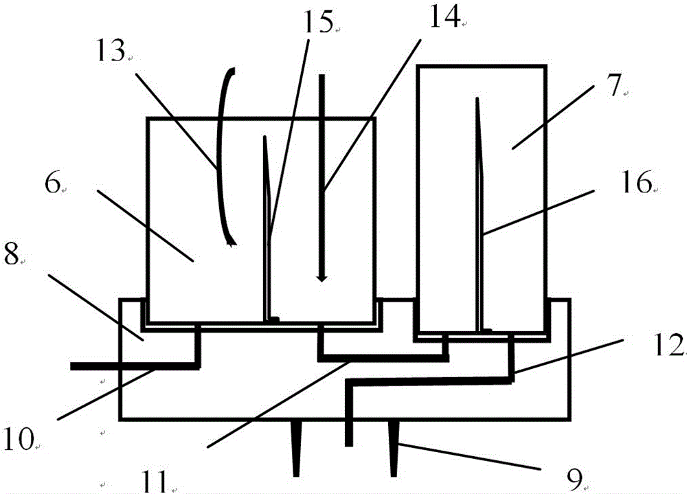
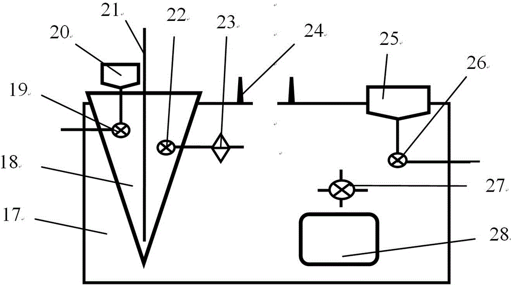
[0024] figure 1 It is a structural block diagram of the radioactive iodine-131 vapor treatment device of the present invention, figure 2 is a schematic structural view of the adsorption device in the present invention, image 3 is a schematic structural view of the alkali absorption device in the present invention, Figure 4 It is a structural schematic diagram of the exhaust gas monitor in the present invention. exist Figure 1~Figure 4 Among them, the radioactive iodine-131 vapor treatment device of the present invention includes an alkali absorption device 1, an adsorption device 2, an exhaust gas monitor 3, a vacuum pump 4, and a temperature controller 5. The connection relationship is that the alkali absorption device 1 is placed in The bottom of the adsorption device 2 is threadedly connected with the adsorption device 2 , the adsorption device 2 , exhaust gas monitor 3 , and vacuum pump 4 are sequentially connected through pipelines, and the adsorption device 2 is e...


PUM


Abstract

The invention provides a radioactive iodine-131 steam treatment set. A production unit comprises an alkali absorption device, an adsorption device, a tail gas monitor, a vacuum pump and a thermostat. The alkali absorption device is disposed below the adsorption device and connected with the same. The adsorption device, the tail gas monitor and the vacuum pump are connected in order through a pipeline. The adsorption device is electrically connected with the thermostat. The radioactive iodine-131 steam treatment set allows iodine-131 steam generated in the production process of Na131I solution to be efficiently treated and allows the tail gas to be discharged within standard. functional parts for the treatment of iodine-131 steam, such as the alkali absorption part, the drying part and the activated carbon absorption part, are integrated, functions of adsorption column heat-degassing and tail gas monitoring are provided, the set is better in tightness, longer in service life, higher in iodine removal efficiency and higher in operating and running safety, and the risk caused by over-standard emission of the tail gas and staff taking more radiation dosage is decreased; the set is compact, small in size and more convenient to handle, use and maintain.

Description

technical field [0001] The invention belongs to the technical field of radioisotope preparation, and in particular relates to a radioactive iodine-131 vapor treatment device. Background technique [0002] At present, sodium iodide (Na 131 I) and the raw material of iodine-131 labeled medicine mainly comes from TeO after irradiation from the reactor 2 and from 235 Extracted by distillation from a mixture of lobes of U. Regardless of the raw material and distillation method (dry method / wet method) used to produce radioactive iodine-131, lye absorption and activated carbon adsorption will be used to treat iodine-131 vapor, that is, the distilled radioactive iodine-131 vapor (generally Using air as the carrier gas) successively passes through the absorption bottle of dilute alkali solution (such as NaOH solution with a concentration of less than 0.5mol / L) and the absorption bottle of concentrated alkali solution (such as NaOH solution with a concentration greater than 4mol / L)...

Claims


Application Information

Patent Timeline
Patent Type & Authority Patents(China)
IPC IPC(8): G21F9/02
CPCG21F9/02
Inventor 刘国平源魏洪陈静陈琪萍何佳恒王关全李梅李兴亮吴川党宇峰牟婉君刘飞余钱红张锐钟文彬蹇源
Owner INST OF NUCLEAR PHYSICS & CHEM CHINA ACADEMY OF
Why Eureka
Try Eureka