High-precision pulsed power supply adjusting device and method based on frequency domain

A technology of pulse power supply and pulse regulation, applied in control/regulation systems, instruments, simulators, etc., can solve the problem of large storage space of pulse power supply, and achieve the effect of high regulation accuracy

Active Publication Date: 2015-04-29
QXP TECH INC
View PDF15 Cites 3 Cited by
  • Summary
  • Abstract
  • Description
  • Claims
  • Application Information

AI Technical Summary

Problems solved by technology

Using the above traditional method to improve the adjustment accuracy of the pulse power supply requires a large storage space to save the pulse waveform file. To generate a new waveform, the waveform file needs to be updated.

Method used


Image

  • High-precision pulsed power supply adjusting device and method based on frequency domain
  • High-precision pulsed power supply adjusting device and method based on frequency domain
  • High-precision pulsed power supply adjusting device and method based on frequency domain

Examples


Embodiment Construction

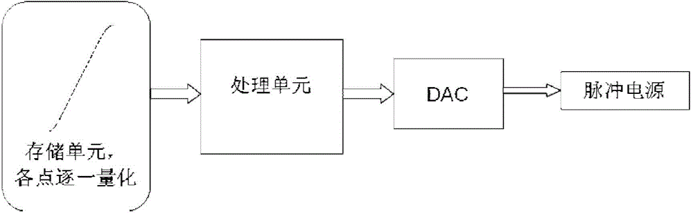
[0032] The invention converts the relationship of time-voltage amplitude into the relationship of frequency-voltage amplitude, establishes the corresponding relationship between pulse count and output voltage value, and generates the required pulse waveform by controlling the frequency change. The invention can realize high voltage control precision, and the calculation process is simple, only needing a multiplier and addition / subtraction. Its controller structure is as follows image 3 Shown: by direct digital frequency synthesizer DDS, programmable device FPGA, high-precision digital / analog converter DAC. Among them, DDS produces waveforms of different frequencies. The DAC outputs an analog signal. FPGA is a control unit and a calculation unit. FPGA is used as a control unit to realize the control of DDS and DAC, and as a calculation unit to realize the frequency-amplitude algorithm.

[0033] FPGA program design block diagram as Figure 9 As shown, the DDS interface mo...


PUM


Abstract

The invention provides a high-precision pulsed power supply adjusting device based on frequency domain, which comprises a DDS (Direct Digital synthesizer), an FPGA (Field Programmable Gate Array) and a high-precision DAC (Digital-to-Analog Converter), wherein the DDS generates waveforms with different frequencies; the high-precision DAC outputs an analog signal; the FPGA is a control unit and an arithmetical unit; the FPGA as the control unit can control the DDS and the DAC, and the FPGA as the arithmetical unit can realize a frequency-amplitude algorithm. The high-precision pulsed power supply adjusting device based on the frequency domain solves the contradiction between high-precision pulsed power supply adjustment and large memory space.

Description

technical field [0001] The invention relates to a pulse power regulator, in particular to a high-precision pulse power regulator based on frequency domain. Background technique [0002] Pulse power supply is widely used in ion accelerators. The traditional pulse power supply controller consists of figure 1 Shown: high-speed high-precision digital / analog converter DAC, micro control unit MCU, non-volatile memory Flash. As the structure of the controller adopted in the patent CN101581920A. This structure works as figure 2 Shown: 1. A look-up table is generated according to the pulse waveform, and the value of the look-up table is the output voltage value of the DAC at time t, that is, y=f(t). 2. Update the value of the lookup table to Flash. 3. A pulse period starts after the MCU receives the trigger signal. 4. The MCU reads out the corresponding voltage value from the Flash according to the time t. 5. The MCU controls the DAC output, and its working process is as fol...

Claims


Application Information

Patent Timeline
Patent Type & Authority Applications(China)
IPC IPC(8): G05B19/042
CPCG05B19/042G05B2219/26
Inventor 黄继江曹剑中王泽峰廖加文
Owner QXP TECH INC
Why Eureka
Try Eureka