
Thin wide-angle four-piece imaging lens set

An imaging lens, four-piece technology, applied in the field of imaging lens groups, can solve the problem of not being able to further meet the thin, wide-angle, etc., and achieve the effect of improving the resolution.

Active Publication Date: 2015-04-29
ABILITY OPTO ELECTRONICS TECH
View PDF11 Cites 18 Cited by
  • Summary
  • Abstract
  • Description
  • Claims
  • Application Information

AI Technical Summary

Problems solved by technology

[0003] However, the existing imaging lens groups, such as Chinese Taiwan patents TW201215941A, TW201224568A, TW201239443A, etc., although revealing a four-piece imaging lens group, the implementation of the previously disclosed patents failed to further meet the thin and wide-angle requirements.

Method used


Image

  • Thin wide-angle four-piece imaging lens set
  • Thin wide-angle four-piece imaging lens set
  • Thin wide-angle four-piece imaging lens set

Examples


no. 1 Embodiment

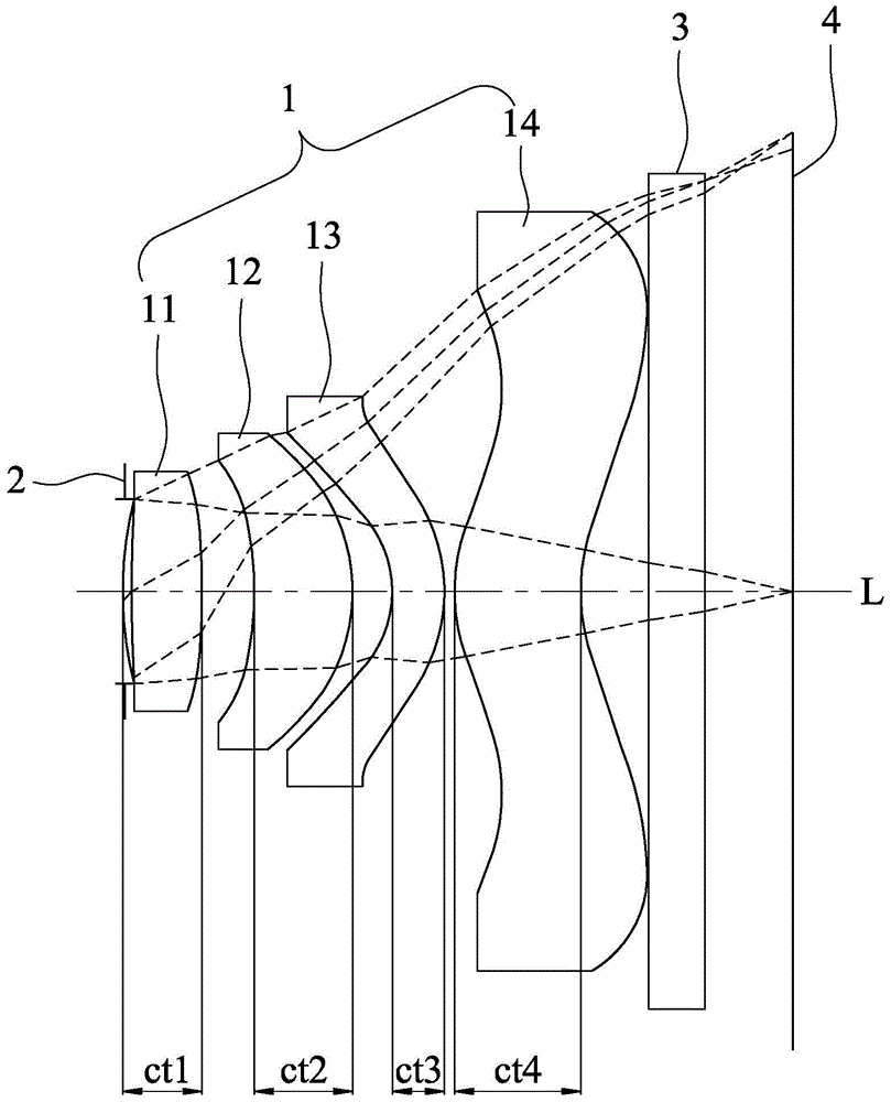
[0060] exist figure 1 Among them, along the central optical axis L from the object side to the image side are the first surface and the second surface of the first lens 11, the third surface and the fourth surface of the second lens 12, and the third surface of the third lens 13. The fifth surface and the sixth surface, and the seventh surface and the eighth surface of the fourth lens 14, the fixed aperture 2 is located between the object side and the second lens 12, that is to say, the fixed aperture 2 can be set Between the first lens 11 and the object side, the fixed diaphragm 2 may also be disposed between the first lens 11 and the second lens 12 . In this embodiment, the fixed diaphragm 2 is located between the object side and the first lens 11 . The lens data corresponding to the first lens 11, the second lens 12, the third lens 13, and the fourth lens 14 are shown in Table 1. The first lens 11, the second lens 12, the third lens 13, the The aspheric parameters corresp...

no. 2 Embodiment

[0068] Cooperate with reference Figure 4 , Figure 5 and Image 6 , and the parameters of the second specific embodiment are: f1=2.39mm, f2=2.08mm, f3=-1.45mm, f4=1.85mm, f=1.60mm, ct1=0.276mm, ct2=0.392mm, ct3=0.204mm, ct4=0.450mm, HFOV=44°. The fixed diaphragm 2 is located between the second surface of the first lens 11 and the second lens 12, and the corresponding lens data of the first lens 11, the second lens 12, the third lens 13, and the fourth lens 14 are shown in the table 3, the aspherical parameters corresponding to the first lens 11, the second lens 12, the third lens 13, and the fourth lens 14 are shown in Table 4.

[0069] The second specific embodiment satisfies conditional formulas (1) to (11) HFOV / f=27.5, |f / f3|=1.10, ct1 / ct2=0.70, ct3 / ct4=0.45, Nd2=1.535, Nd3=1.636, V2=56.07, V3=23.89.

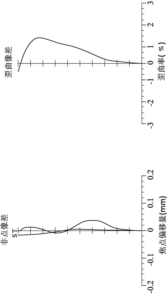
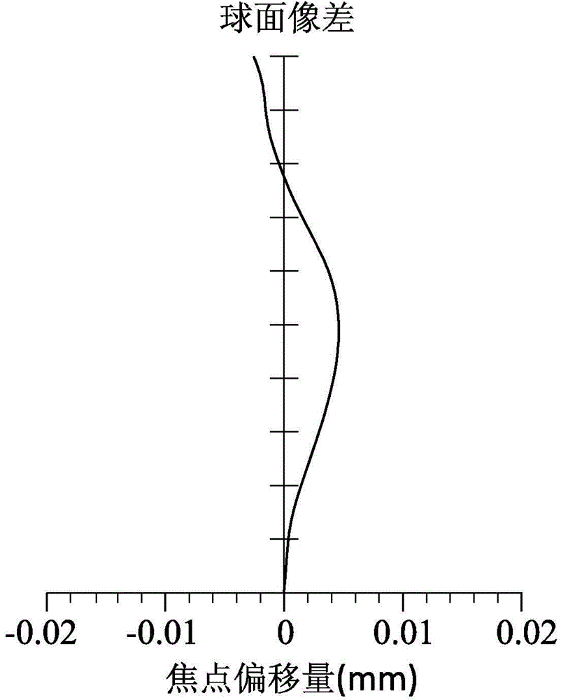
[0070] Figure 5 To express the astigmatism and distortion aberration of the second specific embodiment, Image 6 The spherical aberration of the second embodiment is...

no. 3 Embodiment

[0076] Cooperate with reference Figure 7 , Figure 8 and Figure 9 , and the parameters of the third specific embodiment are: f1=2.55mm, f2=0.86mm, f3=-0.61mm, f4=0.98mm, f=1.13mm, ct1=0.239mm, ct2=0.266mm, ct3=0.187mm, ct4=0.429mm, HFOV=44°, the fixed diaphragm 2 is located between the object side and the first surface of the first lens 11, the first lens 11, the second lens 12, the third lens 13. The lens data corresponding to the fourth lens 14 are shown in Table 5, and the aspheric parameters corresponding to the first lens 11, the second lens 12, the third lens 13, and the fourth lens 14 are shown in Table 6.

[0077] The third specific embodiment satisfies conditional formulas (1) to (11) HFOV / f=39.0, |f / f3|=1.85, ct1 / ct2=0.90, ct3 / ct4=0.44, Nd2=1.535, Nd3=1.636, V2=56.07, V3=23.89.

[0078] Figure 8 Expressing the astigmatism and distortion of the third embodiment, Figure 9 The spherical aberration of the third embodiment is expressed.

[0079] table 5

[008...


PUM


Abstract

A thin wide-angle four-piece imaging lens set comprises an optical set and a fixed diaphragm, wherein the optical set sequentially comprises a first lens, a second lens, a third lens and a fourth lens from an object side to an image side along a central optical axis, the refractive power of the first lens, the second lens, the third lens and the fourth lens is positive, positive, negative and positive respectively, the first lens and the third lens face the object side, the parts, close to the central optical axis, of the first lens and the third lens are a convex surface and a concave surface respectively, the second lens faces the image side, the part, close to the central optical axis, of the second lens is a convex surface, the third lens faces the image side, the part, close to the central optical axis, of the third lens is a convex surface, the fourth lens faces the image side, the part, close to the central optical axis, of the fourth lens is a concave surface, and at least one inflection point is located from the central optical axis to an aspheric-surface termination point of the fourth lens; the fixed diaphragm is located between the object side and the second lens. The lens set meets the condition that the quotient of HFOV (high-frequency oscillatory ventilation) divided by f is larger than 15 and smaller than 50, HFOV is half of the largest viewing angle used by the lens set, and f is a focal length value of the imaging lens set; the whole imaging lens set can be more compact and the resolving power is improved due to the facts that a value of HFOV is large and a value of f is small; meanwhile, the imaging lens set has the advantages that the imaging lens set is light, thin, short, small and high in efficiency.

Description

technical field [0001] The invention relates to an imaging lens group, in particular to a thin wide-angle four-chip imaging lens group. Background technique [0002] The existing imaging lens group is suitable for imaging lens groups in electronic products such as mobile phones, smart phones, tablet computers, notebook computers, and cameras. With the continuous development of such electronic products, there is a tendency of thinner and smaller design gradually, but at the same time, high performance is required. Therefore, the imaging lens group is developed towards a thinner and more compact overall size. In order to improve the resolution, the imaging The lens group also needs to develop towards a wider angle. [0003] The existing imaging lens sets, such as Chinese Taiwan patents TW201215941A, TW201224568A, TW201239443A, etc., although disclose a four-piece imaging lens set, the implementation of the previously disclosed patents can not further meet the thin and wide-an...

Claims


Application Information

Patent Timeline
Patent Type & Authority Applications(China)
IPC IPC(8): G02B13/18G02B13/06
CPCG02B13/004G02B13/06G02B13/18
Inventor 游鸿国杨朝翔
Owner ABILITY OPTO ELECTRONICS TECH
Learn More