
Backlight module with diffraction optical element

A technology of diffractive optical elements and backlight modules, applied in optical elements, optics, nonlinear optics, etc., can solve the problems of thick lens thickness, insufficient light transmittance of light-transmitting plate, limited range accuracy of lens surface, etc. cost effect

Inactive Publication Date: 2008-03-05
IND TECH RES INST
View PDF5 Cites 0 Cited by
  • Summary
  • Abstract
  • Description
  • Claims
  • Application Information

AI Technical Summary

Problems solved by technology

However, the curved surface of the lens in this method is limited by the precision of the manufacturing process, so it is difficult to manufacture, and the thickness of the lens is also relatively thick, resulting in a substantial increase in the thickness of the backlight module; First guide the light from the light source to the diffuser, and then spread the light evenly to the LCD panel through the diffuser
In this way, due to the lack of light transmission of the light-transmitting plate itself, and the problem of uniform diffusion must be considered at the same time, it is impossible to reduce the thickness of the overall backlight module under the multi-layer board configuration.

Method used


Image

  • Backlight module with diffraction optical element
  • Backlight module with diffraction optical element
  • Backlight module with diffraction optical element

Examples


Embodiment Construction

[0016] In order to make the above objects, features and advantages of the present invention more comprehensible, preferred embodiments are listed below and described in detail in conjunction with the accompanying drawings.

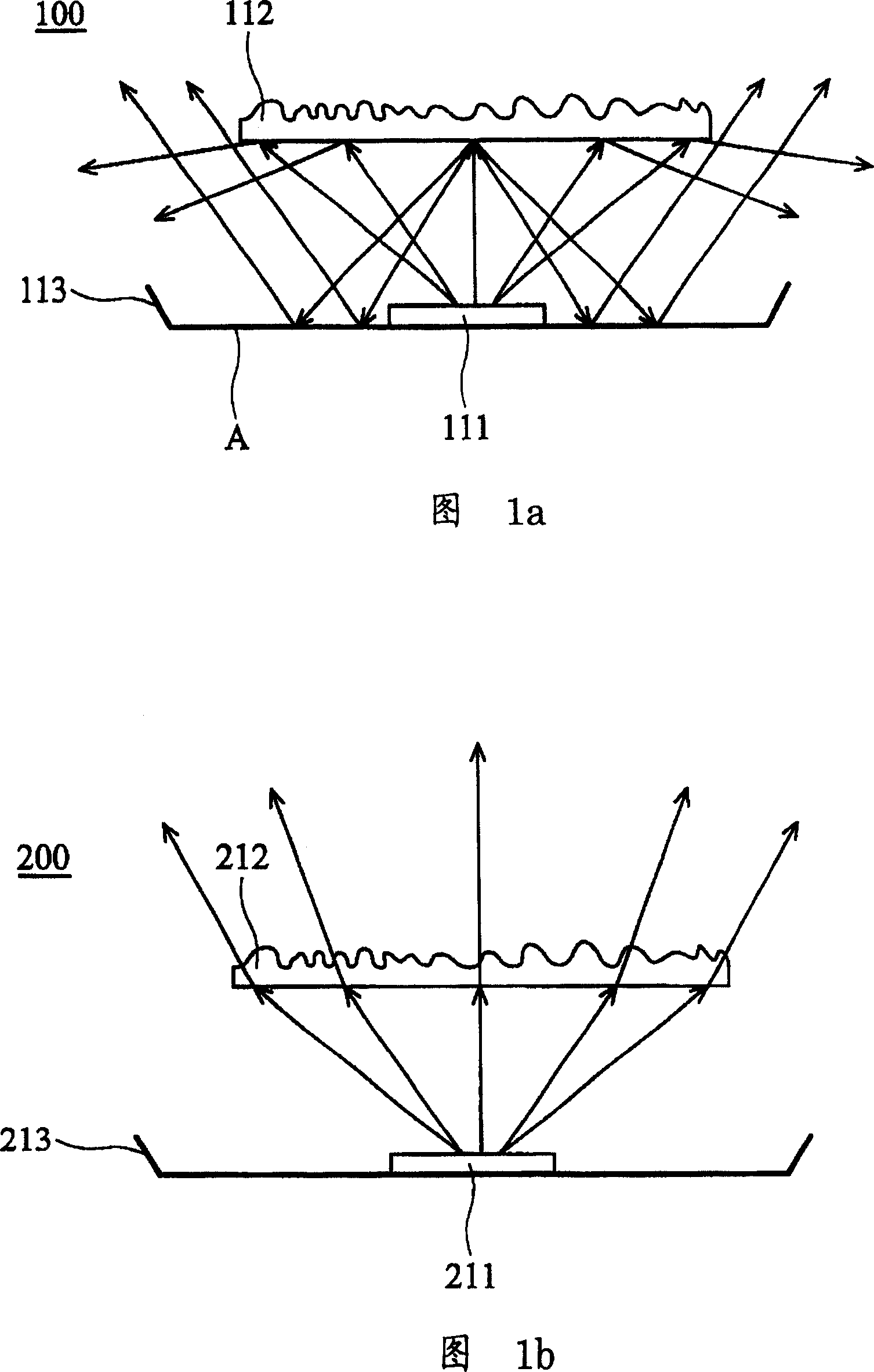
[0017] See Figure 1a first. FIG. 1a shows a schematic diagram of a first embodiment of a backlight module of the present invention. In this embodiment, the backlight module of the present invention is a direct type backlight module 100 , including: a liquid crystal panel (not shown in the figure), a light source 111 , a reflector 113 , and a diffractive optical element 112 . Since the remaining elements are not essential features of the invention, they are not all listed. Wherein, the diffractive optical element 112 is arranged above the light source 111. Through proper phase configuration, the diffractive optical element 112 can modulate the wavefront of the light wave emitted by the light source 111, and then control the direction and distribution of li...


PUM


Abstract

The invention discloses a negative phototropic mode of diffraction optics element, which consists of light source and diffraction optics element, wherein the diffraction optics element is set on the light source to adjust the wave front from light source, which controls the light direction and distribution through adequate phase match; the negative phototropic mode can reach the goal of light, thin, short and small by regarding the light uniformity and maximum; the diffraction optics element refracts ray without being folded geometrical shape, which simplifies the manufacturing course and reduces the cost.

Description

technical field [0001] The invention relates to a backlight module, in particular to a backlight module which uses a diffractive optical element to control the distribution and intensity of a diffused light source. Background technique [0002] Currently, it is known that the light source of a light emitting diode (LED) backlight module diffuses, mainly by adding a specially designed lens on the light emitting diode. Such as the backlight module disclosed in U.S. Patent No. 6679621B2LUMILEDS, wherein the edge-emitting light-emitting diodes in the LUMILEDS backlight module are installed on the light-emitting diodes with special optical lenses to enhance their edge-emitting uniform light mixing. Effect. However, the curved surface of the lens in this method is limited by the precision of the manufacturing process, so it is difficult to manufacture, and the thickness of the lens is also relatively thick, resulting in a substantial increase in the thickness of the backlight mod...

Claims


Application Information

Patent Timeline
Patent Type & Authority Patents(China)
IPC IPC(8): G02F1/1335G02B5/00
Inventor 吕英宗黎邦伍清钦曲昌盛
Owner IND TECH RES INST
Learn More