
zoom lens

A zoom lens and lens technology, applied in the field of zoom lenses, can solve problems such as inability to effectively meet market demands, imperfect zoom lens design, and poor brightness perception.

Active Publication Date: 2019-04-19
CALIN TECH
View PDF9 Cites 0 Cited by
  • Summary
  • Abstract
  • Description
  • Claims
  • Application Information

AI Technical Summary

Problems solved by technology

However, when the current optical photosensitive element uses more than 5 million pixels, no matter how small the single pixel size is, it will cause poor brightness. Therefore, the design size of the optical photosensitive element will become larger, but after the size is increased, Usually, for better design and manufacture, the size of the lens will be enlarged accordingly, resulting in higher production cost, which runs counter to the market demand
[0005] Therefore, it can be seen from the above description that when the market application is developing towards high-resolution high-end applications, the design of the existing zoom lens is still not perfect and cannot effectively meet the market demand, and there is still a risk of improvement

Method used


Image

  • zoom lens
  • zoom lens
  • zoom lens

Examples


Embodiment Construction

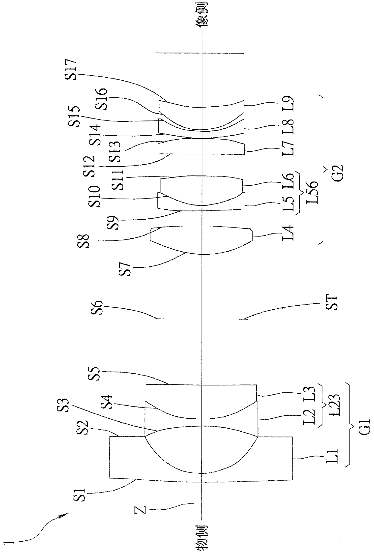
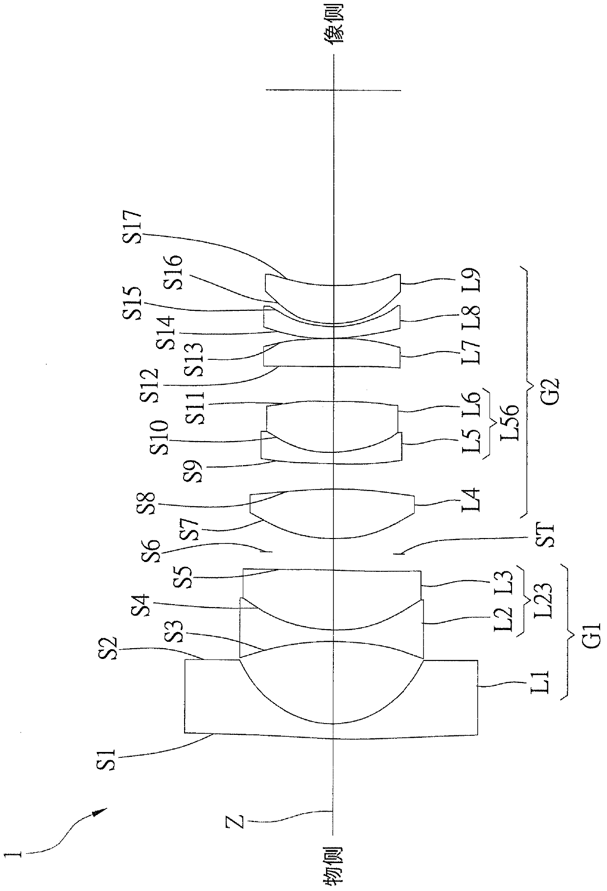
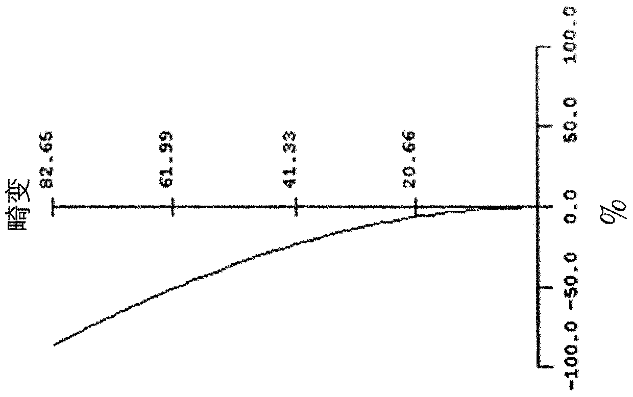
[0061] In order to illustrate the present invention more clearly, the following examples are cited and described in detail in conjunction with the drawings, and please refer to Figure 1A and Figure 1B , Figure 3A and Figure 3B , Figure 5A and Figure 5B , Figure 7A and Figure 7B , Figure 9A and Figure 9BShown are the lens structures of the zoom lenses 1 to 5 of the first to fifth embodiments of the present invention at the wide-angle end and the telephoto lens respectively, wherein:

[0062] The zoom lenses 1 - 5 respectively include a first lens group G1 , a diaphragm ST and a second lens group G2 sequentially arranged along an optical axis Z from an object side to an image side. In addition, according to the needs of use, an optical filter (Optical Filter) can also be provided in the middle of the zoom lenses 1-5 (such as the aperture position, between the second lens group G2 and the image side, etc.) to filter The purpose of improving optical performance c...


PUM


Abstract

The invention discloses a zoom lens including a first lens group, an aperture and a second lens group which are sequentially arranged from an object side to an image side. The first lens group has negative refractive power and is composed of a first lens, a second lens and a third lens. The refractive power respectively of the first lens, the second lens and the third lens is sequentially negative, negative and positive, and the third lens and the second lens are adhesively attached together to form a balsaming lens with negative refractive power. The second lens group has positive refractive power and is composed of a fourth lens, a fifth lens, a sixth lens, a seventh lens, an eighth lens and a ninth lens. The refractive power of the fourth lens, the fifth lens, the sixth lens, the seventh lens, the eighth lens and the ninth lens are sequentially positive, negative, positive, positive, negative and positive. The sixth lens and the fifth lens are adhesively attached together to form a balsaming lens with negative refractive power. In addition, the first mirror group is movable between the object side and an aperture, and the second mirror group is movable between the aperture and the image side.

Description

technical field [0001] The present invention relates to an optical lens; in particular, it refers to a zoom lens. Background technique [0002] In recent years, the rapid progress of semiconductor technology has made the images imaged by optical equipment such as monitors more and more detailed, and the resolution and pixel requirements of the lenses of the above optical equipment have also increased. More specifically, When the lens is short-focus, it is required to have a wide viewing angle, and it also needs to meet the requirements of low manufacturing cost, thinness and shortness. [0003] In addition, during the daytime, the lens of the above-mentioned optical equipment uses visible light as the light source for image capture, and at night, it uses near-infrared light as the light source for image capture. The ambient light is too dim. In order to make the picture after imaging have enough brightness, the lens of the above optical equipment usually needs to meet the d...

Claims


Application Information

Patent Timeline
Patent Type & Authority Patents(China)
IPC IPC(8): G02B15/177
Inventor 李明磷曾建雄
Owner CALIN TECH
Learn More