Anti-surge system of centrifugal type refrigerating unit

A refrigeration unit and anti-surge technology, which is applied in the direction of refrigerators, refrigeration components, refrigeration and liquefaction, etc., can solve the problems of compressor resource waste, reduce system high and low pressure differences, and increase power consumption, so as to avoid resource and energy waste Waste, reduce system pressure difference, high energy utilization effect

Active Publication Date: 2015-04-29
GREE ELECTRIC APPLIANCES INC
View PDF6 Cites 6 Cited by
  • Summary
  • Abstract
  • Description
  • Claims
  • Application Information

AI Technical Summary

Problems solved by technology

When the surge phenomenon of the compressor unit is predicted, the hot gas bypass valve is opened to conduct conduction, and the high-temperature and high-pressure refrigerant gas directly enters the evaporator, reducing the high-low pressure difference of the system, and at the same time increasing the suction and discharge capacity of the compressor, so that the compression The unit is far away from the surge point, but this control method has the following problems: (1) The high-temperature and high-pressure gaseous refrigerant enters the evaporator at a very high flow rate, accompanied by loud noise; (2) The increase of the suction and discharge volume of the compressor causes Power consumption increases, but because the gaseous refrigerant passing through the condenser has no cooling effect, the compressor will waste resources on its work, and the performance coefficient of the compressor will be greatly reduced; (3) subject to the specifications of the solenoid valve and the bypass Influenced by factors such as pipeline diameter, the hot gas bypass capacity of the compressor unit is limited. For larger units, the proportion of hot gas bypass effect will be reduced. It's often just a drop in the bucket

Method used


Image

  • Anti-surge system of centrifugal type refrigerating unit
  • Anti-surge system of centrifugal type refrigerating unit

Examples


Embodiment Construction

[0025] The technical solutions of the present invention will be further described below in conjunction with the accompanying drawings and through specific implementation methods.

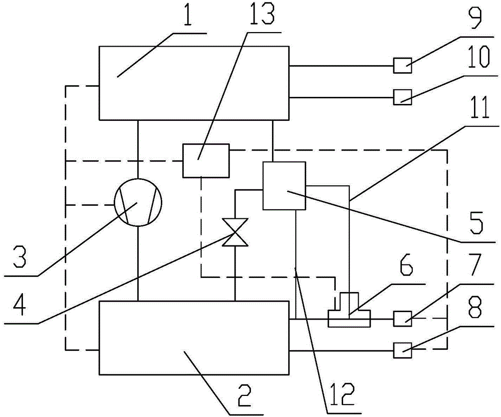
[0026] Such as figure 1 Shown is the specific connection structure of the anti-surge system of the centrifugal refrigeration unit proposed in the specific embodiment of the present invention. The connection mode between the various components in the refrigerating unit in the present invention is roughly the same as that of the refrigerating unit in the prior art, including a condenser 1 and an evaporator 2, and the condenser 1 and the evaporator 2 are respectively connected There is a compressor 3 and a throttling device 4 . The condenser 1 is connected with a cooling water outlet 9 and a cooling water inlet 10. The cooling water inlet 10 is used for the external cooling water to enter the condenser 1 and exchange heat with the refrigerant in the condenser 1. The cooling water outlet 9 It is used ...


PUM


Abstract

The invention relates to the field of an anti-surge structure, discloses an anti-surge system of a centrifugal type refrigerating unit, the anti-surge system of the centrifugal type refrigerating unit is characterized in that a compressor and a throttling device are respectively connected between a condenser and an evaporator, a boost branch for reducing the pressure difference between the condenser and the evaporator is arranged between the throttling device and a frozen water inlet; the boost branch contains a heat exchange device, the heat exchange device has a refrigerant passage and a water passage, the refrigerant passage is in communication with the condenser and the throttling device, the water passage is in communication with the frozen water inlet and the evaporator, and the water entering from the frozen water inlet in the heat exchange device exchanges heat with the refrigerant out of the condenser. The boost branch is arranged for reducing the pressure difference between the condenser and the evaporator and the heat exchange device is arranged in the boost branch, so that the system pressure difference between the condenser and the evaporator is effectively reduced, and the problem that the noise is generated when a hot gas bypass valve is open in the prior art is avoided.

Description

technical field [0001] The invention relates to the field of anti-surge structures, and more specifically discloses an anti-surge system applied to centrifugal refrigeration units. Background technique [0002] As a speed compressor, the centrifugal refrigeration compressor has an inherent characteristic of surge phenomenon during operation. For refrigeration central air-conditioning units that use centrifugal compressors, attention must always be paid to avoid surges during their design and actual use. [0003] The mechanism of the surge phenomenon during the operation of the compressor is roughly divided into two categories: one is high pressure difference; the other is low flow. Due to the above two factors, during the operation of the compressor, the inlet guide vane of the compressor unit adjusts the gas flow and the motor speed adjustment of the frequency conversion unit needs to be properly restricted in order to avoid the occurrence of surge phenomenon, so to a cert...

Claims


Application Information

Patent Timeline
IPC IPC(8): F25B1/00F25B41/04F25B41/06F25B49/02F25B41/20F25B41/30
CPCF25B1/00F25B49/02F25B2500/13F25B2500/12F25B41/30F25B41/20Y02B30/70
Inventor 周宇李宏波张治平周堂万亮刘贤权
Owner GREE ELECTRIC APPLIANCES INC
Why Eureka
Try Eureka