A heating-type turbulent laminar fluidization drag-reducing fluid transport pipeline and method thereof

A drag-reducing fluid and turbulent layer technology, applied in the direction of fluid flow, pipeline heating/cooling, pipes, etc., can solve problems such as uncontrolled pipeline flow, achieve high heating power, high heat-resistant temperature, and reduce fluid transportation energy consumption Effect

Inactive Publication Date: 2016-06-15
ZHEJIANG UNIV
View PDF5 Cites 2 Cited by
  • Summary
  • Abstract
  • Description
  • Claims
  • Application Information

AI Technical Summary

Problems solved by technology

[0004] In skin effect heat tracing, the energy loss in fluid transport is reduced by reducing the viscosity, but there is no control over the flow in the pipe

Method used


Image

  • A heating-type turbulent laminar fluidization drag-reducing fluid transport pipeline and method thereof
  • A heating-type turbulent laminar fluidization drag-reducing fluid transport pipeline and method thereof
  • A heating-type turbulent laminar fluidization drag-reducing fluid transport pipeline and method thereof

Examples


Embodiment Construction

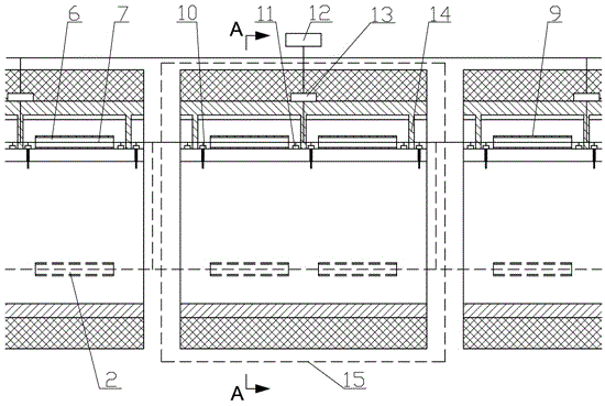
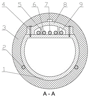
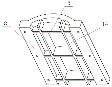
[0018] as attached figure 1 , 2 , 3, the heat-tracing type turbulent laminar fluidization drag-reducing fluid transport pipeline is composed of a plurality of single-section transportation pipelines 15 and a general controller 12, and the single-section transportation pipeline 15 includes an arcuate pipeline 1, a fluid electric heating pipe 2. Insulation layer 3, bolts 4, axial ribs 5, pipe wall electric heat tracing pipe 6, insulated wire 7, pipe upper cover 8, heat tracing steel pipe 9, fluid temperature monitoring device 10, wall temperature monitoring device 11, temperature control 13 and radial ribs 14; the arched pipes are connected by welding or flanges, the section of the arched pipes is a bow with the chord at the top, and the arc length is longer than a semicircle, and the upper cover 8 of the pipe is connected to the upper surface of the bowed pipe chord through the bolts 4 on both sides. The inner side of the upper cover of the pipe is provided with an axial reinf...


PUM


Abstract

The invention discloses a heat tracing turbulent layer fluidized drag-reducing flow conveying pipe and a method thereof. The heat tracing turbulent layer fluidized drag-reducing flow conveying pipe is formed by a plurality of single-section conveying pipes and a master controller. Each single-section conveying pipe mainly includes an arched pipe, a fluid heat tracing pipe, an insulating layer, a pipe wall heat tracing pipe, a pipe upper cover, a fluid temperature monitoring device, a wall temperature monitoring device and a temperature controller. The heat tracing turbulent layer fluidized drag-reducing flow conveying pipe aims at existing heating conveying of high-viscous and congealable fluid, combines the existing skin effect heat tracing technology and the fluid drag reducing control technology by aid of the design of the round conveying pipe arched fluid interface, and achieves control on the fluidized flow state of the fluid turbulent layer in the pipe near the fluid string surface on the basis of the congeal removing and viscosity reducing effects of the skin effect heat tracing technology by maintaining the temperature difference of the wall surface of the arched pipe and the fluid in the pipe. Thus, pressure drop loss of fluid during conveying can be further reduced, the conveying efficiency can be improved, and energy saving and consumption reducing can be promoted.

Description

technical field [0001] The invention relates to a heat-tracing type turbulent laminar fluidization drag-reducing fluid transport pipeline and its method, especially in the field of fluid transport, which is easy to condense or has a high viscosity at normal temperature, and becomes liquid or has a reduced viscosity after heating. Heat-tracing turbulent laminar fluidization drag-reducing fluid transport pipeline. Background technique [0002] There are four ways to transport industrial products or raw materials such as liquids or gases: road, rail, water and pipeline. Compared with other types, pipeline transportation has the characteristics and outstanding advantages of large transportation volume, less land occupation, airtight safety, easy management, high reliability, low energy consumption and low freight cost, so it has become the first choice for liquid or gas transportation. an ideal way. [0003] Long-distance transportation pipelines are divided into two types: is...

Claims


Application Information

Patent Timeline
Patent Type & Authority Patents(China)
IPC IPC(8): F16L9/22F16L53/00F15D1/06
CPCF15D1/06F16L9/22F16L53/34
Inventor 俞自涛田付有钱虹良翁元凯范利武黄连锋朱子钦李佳琦
Owner ZHEJIANG UNIV
Why Eureka
Try Eureka