A multi-purpose valve device

A multi-purpose, valve device technology, applied in valve devices, multi-way valves, valve heating/cooling devices, etc., can solve the problems of inaccurate control of outlet flow, single inlet and outlet, and inability to save water. It achieves the effect of simple structure, convenient operation and preventing the outlet from freezing

Inactive Publication Date: 2016-10-26
黄卫科
View PDF5 Cites 0 Cited by
  • Summary
  • Abstract
  • Description
  • Claims
  • Application Information

AI Technical Summary

Problems solved by technology

At present, the water valves used in pipelines, whether they are household or business, are known to be composed of a single inlet and an outlet, especially the flow rate of water flowing out from the outlet can only be adjusted by people's hand to twist the outlet switch. In this way, the flow of the outlet cannot be accurately controlled, let alone save water, so it is necessary to propose an improvement

Method used


Image

  • A multi-purpose valve device
  • A multi-purpose valve device
  • A multi-purpose valve device

Examples


Embodiment Construction

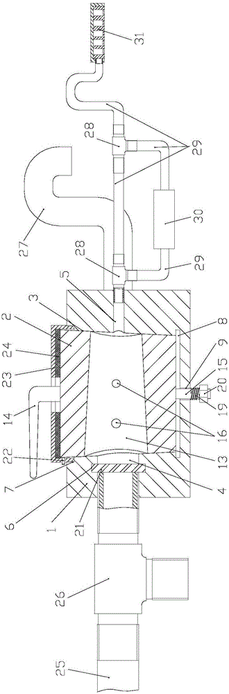
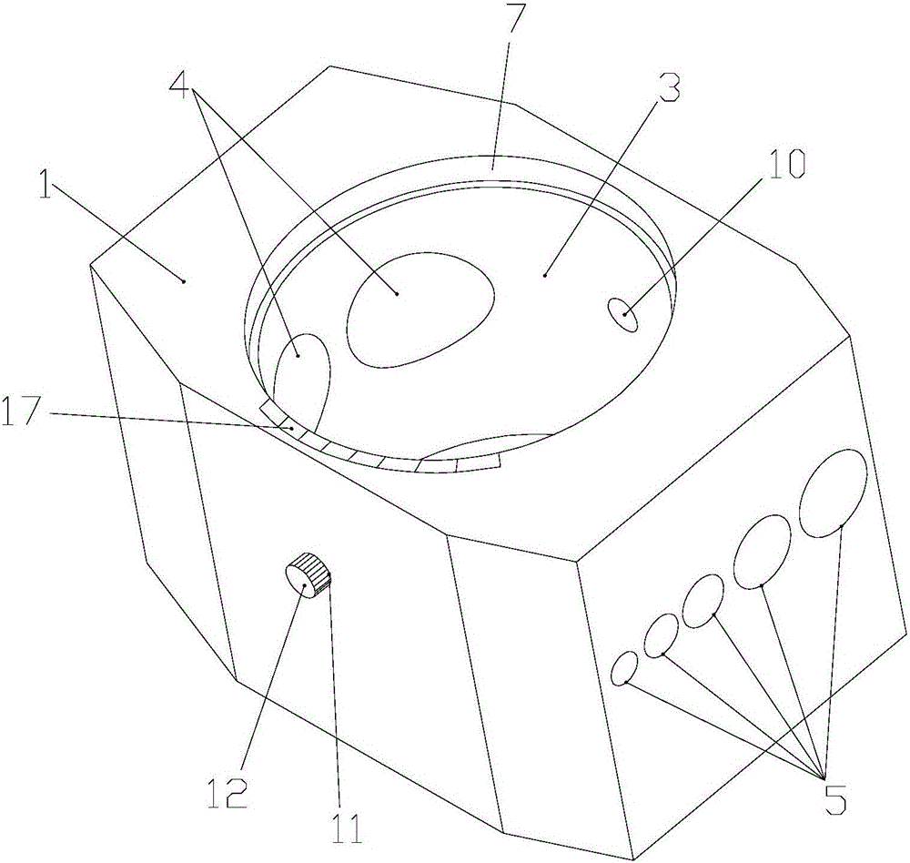
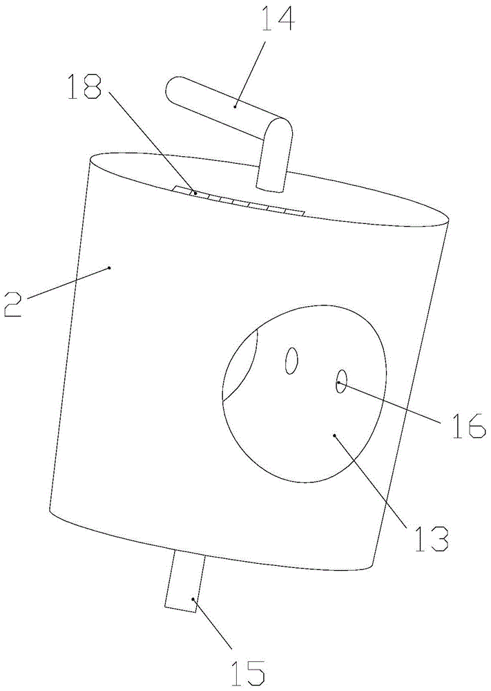
[0025] Attached below Figure 1-6 Embodiments of the present invention are described.

[0026] A multi-purpose valve device has a valve body 1 and a valve core 2. The valve body 1 is provided with a valve body check 3 and its inner surface is conical. The outer surface of the valve core 2 is conical and is in line with the valve The inner conical surface of the body seam 3 is tightly fitted, and the top of the valve body seam 3 is shaped on a prism 7 and the inner cylindrical surface of the ridge 7 is formed with a screw thread that is screwed with the valve core cover 23, and the valve core The cover 23 is formed with a top wire hole and the top wire 22 is screwed with the top wire hole to tighten the outer conical surface of the spool 2. A gasket 24 is arranged between the spool cover 23 and the spool 2, and the spool 2 The top is provided with a spool handle 14 bent at 90°, one end of the spool handle 14 passes through the spool cover 23 and the gasket 24 and is connected ...


PUM


Abstract

The invention provides a multi-purpose valve device. The device comprises a valve body and a valve element; a spigot is formed in the valve body and is closely clung to the outer tapered surface of the valve element; the valve element is compressed into the spigot through a valve element core and a sealing pad; a rod arranged at the bottom part of the valve element passes through a hole in the bottom part of the valve rod and then extends out from the valve body; a spring is arranged on the rod; a nut is screwed to threads in the rod to compress the spring; a plurality of inlets are formed in one end of the valve body, and while a plurality of outlets are formed in the other end of the valve body; filters are arranged in the inlets; each inlet is connected with a solution source or an air source through a pipe joint or a connecting pipe; each outlet is connected with a water faucet or a spiral groove injection head through the pipe joint and the connecting pipe. According to the multi-purpose valve device, the valve element communicates with one or a plurality of inlets and one or a plurality of outlets of different specifications in the valve body to control solution flow rate as requirement; the device has the advantages of being simple in structure and convenient to operate; people can accurately control the dosage and save the resource.

Description

technical field [0001] The invention belongs to the technical field of valve manufacture, and in particular relates to a multipurpose valve device. Background technique [0002] With the continuous development of society, water resources are becoming more and more important, especially in our country where fresh water resources are not very rich, saving water has become a major issue that people are very concerned about. At present, the water valves used in pipelines, whether they are household or business, are known to be composed of a single inlet and an outlet, especially the flow rate of water flowing out from the outlet can only be adjusted by people's hand to twist the outlet switch. In this way, the flow of the outlet cannot be accurately controlled, let alone save water, so it is necessary to propose improvements. Contents of the invention [0003] The technical problem to be solved by the present invention is to provide a multi-purpose valve device, by providing ...

Claims


Application Information

Patent Timeline
Patent Type & Authority Patents(China)
IPC IPC(8): F16K11/076F16K49/00F16K3/30
CPCF16K3/30F16K11/076F16K49/002
Inventor 黄卫科
Owner 黄卫科
Why Eureka
Try Eureka