Timing chain transmission system and engine

A chain transmission and engine technology, applied in the direction of engine components, machines/engines, mechanical equipment, etc., to achieve the effect of reducing assembly costs, reducing friction loss, and prolonging the service life

Active Publication Date: 2015-04-29
SAIC MOTOR +1
View PDF7 Cites 1 Cited by
  • Summary
  • Abstract
  • Description
  • Claims
  • Application Information

AI Technical Summary

Problems solved by technology

[0006] The technical problem to be solved by the present invention is to provide a timing chain transmission system that can largely overcome the defects of displacement, vibration, noise, etc.

Method used


Image

  • Timing chain transmission system and engine
  • Timing chain transmission system and engine
  • Timing chain transmission system and engine

Examples


Embodiment Construction

[0026] Specific embodiments of the present invention will be described in detail below in conjunction with the accompanying drawings.

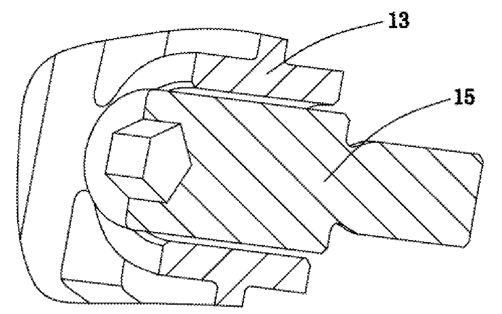
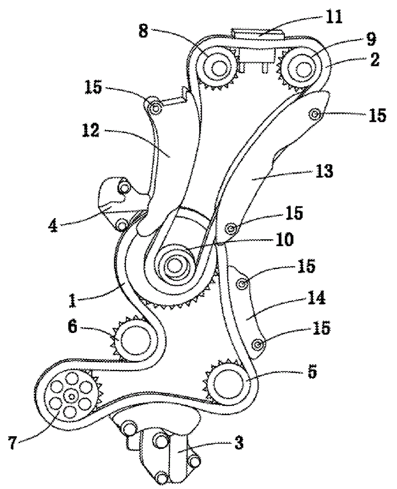
[0027] figure 1 A schematic diagram of a timing chain drive system according to an embodiment of the present invention is shown. exist figure 1 Among them, reference numeral 1 denotes a primary transmission chain, 2 denotes a secondary transmission chain, 3 denotes a primary chain tensioner, 4 denotes a secondary chain tensioner, 5 denotes a crankshaft sprocket, 6 denotes a balance shaft sprocket, 7 represents the oil pump sprocket, 8 represents the intake camshaft sprocket, 9 represents the exhaust camshaft sprocket, 10 represents the idler gear, 11 represents the guide rail between the camshafts, 12 represents the secondary chain tensioner arm, 13 represents the two Grade chain guide rail, 14 represents the first grade chain guide rail, and 15 represents the guide rail bolt.

[0028] As can be seen from the figure, the timing chain transm...


PUM


Abstract

The invention relates to a timing chain transmission system and an engine comprising the system. The timing chain transmission system adopts two-stage transmission including primary chain transmission and secondary chain transmission; power is transmitted between the primary chain transmission and the secondary chain transmission through an idle wheel with two chain wheels. According to the timing chain transmission system and the engine, the assembling cost is reduced, and the service life is prolonged; the severe requirements on all the aspects, such as emission, stability and noise, of the engine can be met.

Description

technical field [0001] The invention relates to the technical field of engine transmission systems; more specifically, the invention relates to an engine timing chain transmission system. [0002] Further, the present invention also relates to an engine comprising the aforementioned timing chain drive system. Background technique [0003] The traditional engine timing drive has three modes: chain drive, toothed belt drive and gear drive. Among them, the chain drive has been widely used in the engine in recent years because of its small footprint, good reliability, maintenance-free and low overall cost. product. [0004] The timing chain drive system of a general engine is usually directly driven by a chain between the crankshaft and the camshaft. In some engines (especially diesel engines), a high-pressure fuel pump (oil pump) is often required for fuel supply, and the drive of the fuel pump also needs to be completed by a chain system; in diesel engines that require a bal...

Claims


Application Information

Patent Timeline
IPC IPC(8): F01L1/348
Inventor 宋国富潘雪伟陈军阮洋陈开浩蒋贵峰何述超宋一飞夏开略
Owner SAIC MOTOR
Why Eureka
Try Eureka