
Tape adhering jig for door frame decorating strip

A technology of adhesive strips and decorative strips, applied in the direction of material gluing, manufacturing tools, connecting components, etc., can solve the problems of insufficient adhesive force, time-consuming attachment, and large deviation of adhesive position, etc., to achieve standardized operations and uniform adhesive force , the effect of effective pasting

Active Publication Date: 2015-04-29
GUANGZHOU MINHUI AUTOMOBILE PARTS
View PDF5 Cites 8 Cited by
  • Summary
  • Abstract
  • Description
  • Claims
  • Application Information

AI Technical Summary

Problems solved by technology

[0002] The decorative strip on the rear door frame needs to be fastened to the car body through adhesive strips, but the production efficiency of pasting the adhesive strip on the decorative strip on the rear door frame has always been low, and the sticking position deviation is large, the sticking force is not enough, and the product quality is poor
The reason for this problem is that this process is completely done manually by workers, which is the bottleneck of the entire assembly process
The worker manually pulls the adhesive strip to fit the decorative strip. While pulling, he needs to visually locate the side of the product as a reference, and finally cut off the adhesive strip with a blade. The whole action takes 9s / Pcs. Because the visual positioning is based on the side of the product, so The position and size of the adhesive strips are unstable, and the adhesive force of the adhesive strips also varies with the strength of the employees.
As mentioned above, in the prior art, it takes a lot of time to attach the decorative strips and rubber strips on the rear door frame, the beat is low, and the position and size of the rubber strips are unstable, the adhesion force is uneven, and there are hidden dangers of quality defects

Method used


Image

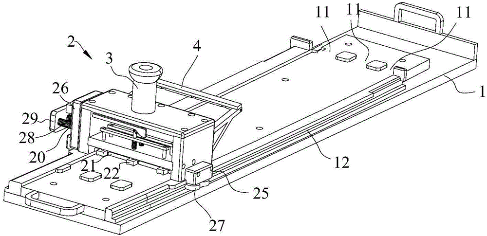
  • Tape adhering jig for door frame decorating strip
  • Tape adhering jig for door frame decorating strip
  • Tape adhering jig for door frame decorating strip

Examples


Embodiment Construction

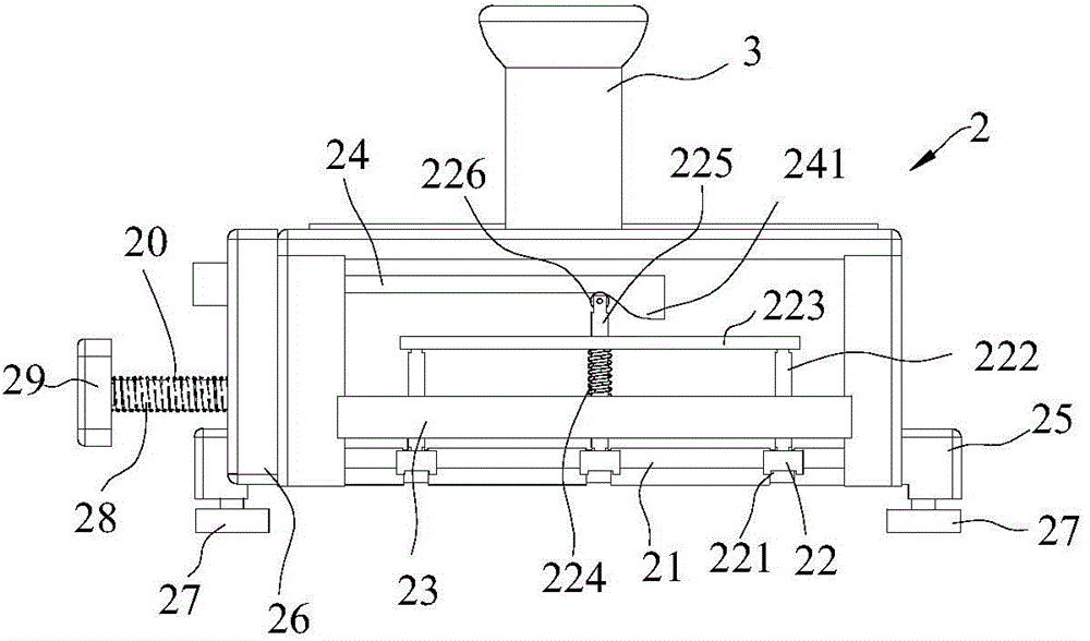
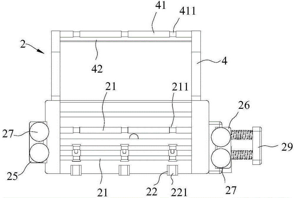
[0016] refer to Figure 1 to Figure 3 , the present invention provides a jig for attaching glue strips on door frame trim, which includes a fixed base 1 and a moving slide 2 that can slide laterally on the fixed base 1, and the top of the moving slide 2 is equipped with Push handle 3. The upper side of the fixed base 1 is provided with three installation positions 11 distributed along the transverse direction to place decorative strips. Rubber strip guide grooves 211 corresponding to each installation position 11 are provided, and a press block 22 corresponding to each installation position 11 is provided on the rear side of the horizontal shaft 21 on the moving slide 2, and the bottom of each press block 22 Rubber strip pressing groove 221 is provided. The moving slide 2 is provided with a guide frame 4 protruding to the front side, and the guide frame 4 is equipped with a guide cross shaft 41 across each installation position 11 and a guide cross bar parallel to the guide ...


PUM


Abstract

The invention discloses a tape adhering jig for a door frame decorating strip. The tape adhering jig for the door frame decorating strip comprises a fixed base, and a moving sliding seat which can transversely slide on the fixing base; a plurality of mounting stations which are transversely distributed to position the decorating strip are arranged at the upper side of the fixing base; transverse shafts which transversely cross each mounting station are mounted at the bottom part of the moving sliding seat; a tape guide groove corresponding to each mounting station is formed in each transverse shaft; a pressing block corresponding to each mounting station is arranged a the rear side of each transverse shaft, on the moving sliding seat; a tape pressing groove is formed in the bottom part of each pressing block. According to the tape adhering jig for the door frame decorating strip, the decorating strip and a tape can be effectively adhered by the moving sliding seat transversely sliding on the fixing base; the plurality of tapes and decorating strips can be adhered synchronously through the plurality of mounting stations at a time, and therefore, the frequency is increased; the operation is standard, the adhering force is uniform, the adverse effect caused by manmade factors can be reduced, and as a result, the quality defect can be removed.

Description

technical field [0001] The invention is used in the field of automobile parts production and manufacturing, and in particular relates to a jig for attaching glue strips on door frame trim strips. Background technique [0002] The decorative strip on the rear door frame needs to be fastened to the car body through adhesive strips, but the production efficiency of pasting the adhesive strip on the decorative strip on the rear door frame has always been low, and the sticking position deviation is large, the sticking force is not enough, and the product quality is poor. The reason for this problem is that this process is completed by pure manual operation of workers, which is the bottleneck of the entire assembly process. The worker manually pulls the adhesive strip to fit the decorative strip. While pulling, he needs to visually locate the side of the product as a reference, and finally cut off the adhesive strip with a blade. The whole action takes 9s / Pcs. Because the visual p...

Claims


Application Information

Patent Timeline
IPC IPC(8): B25B11/00F16B11/00
CPCB25B11/00F16B11/006
Inventor 蒋远富
Owner GUANGZHOU MINHUI AUTOMOBILE PARTS
Learn More