
Sheet metal stamping device

A sheet metal stamping and stamping machine technology, applied in the field of stamping, can solve the problems of high cost, inconvenient installation, complex structure, etc., and achieve the effect of reducing vibration and stress concentration

Active Publication Date: 2017-02-22
福建东帆电机有限公司 +1
View PDF6 Cites 0 Cited by
  • Summary
  • Abstract
  • Description
  • Claims
  • Application Information

AI Technical Summary

Problems solved by technology

The disadvantage of this kind of material guide device is: complex structure, high cost and inconvenient installation, which is not conducive to the stamping machine processing different types of punching parts
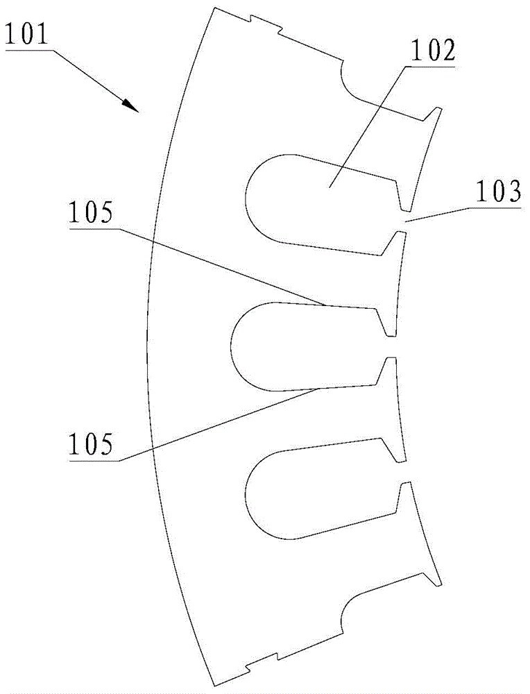
[0003] In addition, in the prior art, the patent No. 200920311064.8 and the patent titled stamping and forming device for stator core sheet disclosed that the single-station blanking punching process is applied to the automatic stamping production of the fan-shaped motor core sheet, and the patent has achieved good results. However, there is no proposal to better solve the adverse effects caused by the uneven gap on both sides of the mold groove formed during mold processing, assembly and blanking.

Method used


Image

  • Sheet metal stamping device
  • Sheet metal stamping device
  • Sheet metal stamping device

Examples


Embodiment Construction

[0025] In order to describe the technical content, achieved goals and effects of the present invention in detail, the following will be described in detail in conjunction with the implementation and accompanying drawings.

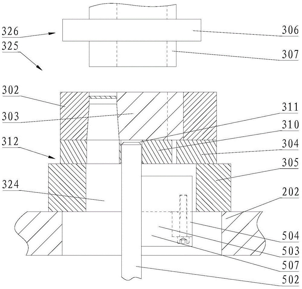
[0026] The most critical idea of ​​the present invention is that the opening of the groove on the fixed molded part and the insert of the groove of the die are designed to be rotationally connected, and the two have a lateral rotation gap at the joint, which can make better use of the groove of the die The side insert is subjected to lateral force, so as to better avoid or reduce the problem of mold damage due to uneven lateral force caused by uneven clearance between both sides of the cutting edge.

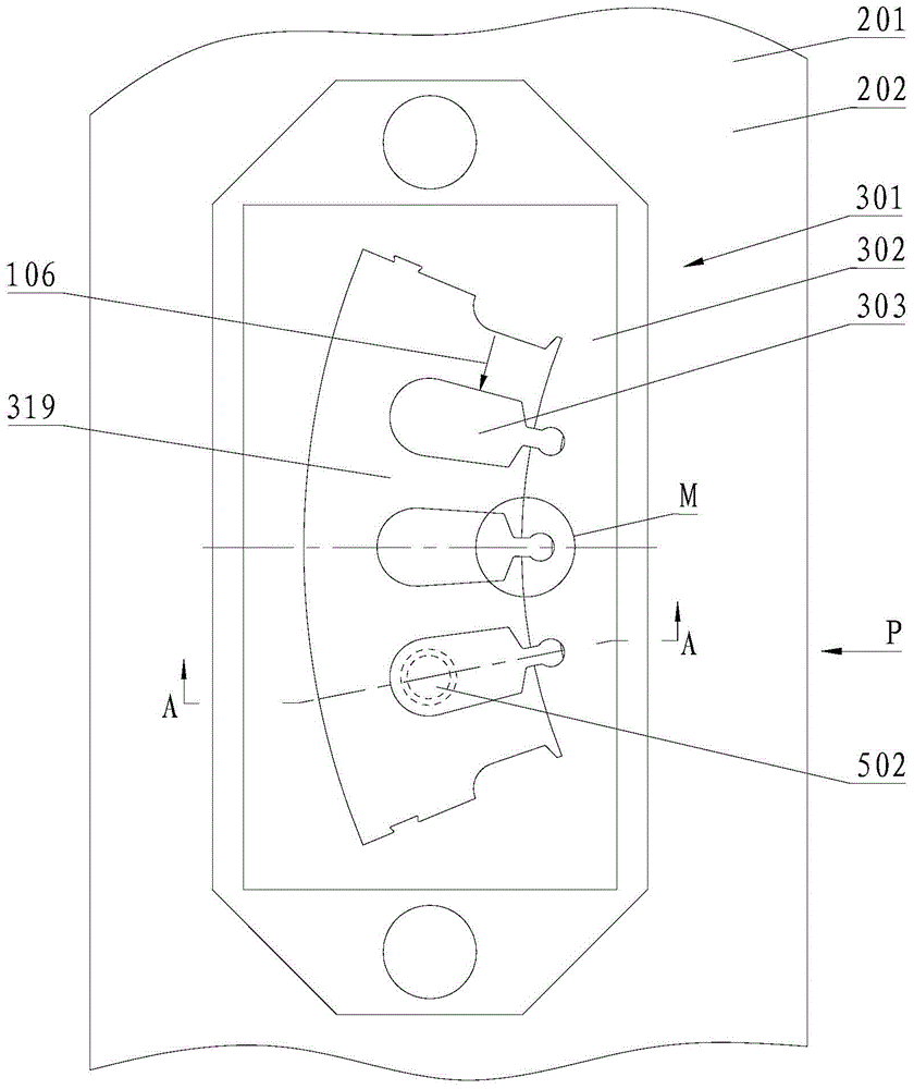
[0027] see Figure 1 to Figure 4 , a sheet metal stamping device, including a stamping machine platform 201 and a stamping die 301 located on the stamping machine platform 201, the stamping die 301 includes a fixed mold forming part 325 and a movable mold form...


PUM


Abstract

The invention discloses a sheet punching device which comprises a punching machine platform and a punching mould arranged on the punching machine platform, wherein a fixed mould forming part comprises a concave mould, a concave mould slot insert block and a slot opening; the concave mould is provided with a concave mould forming cavity; the concave mould slot insert block is provided with a rotating connecting structure; the concave mould slot insert block is connected with the slot opening through the rotating connecting structure, so that the concave mould slot insert block is mounted in the concave mould forming cavity; a lateral rotating gap is arranged for the rotating connecting structure and the slot opening; the concave mould slot insert block is used for forming a slot part of an opening slot distributed at an outer edge of a punched part; the fixed mould forming part is mounted on a fixed platform of the punching machine platform; a blanking channel is arranged under the fixed mould forming part. The sheet punching device has the beneficial effects that the problem of mould damage caused by uneven lateral stress of the concave mould slot resulted from uneven gaps on two sides of a blade is avoided or reduced.

Description

technical field [0001] The invention relates to the stamping field, in particular to a plate stamping device. Background technique [0002] During the stamping process of stamping parts with small opening grooves distributed on the outer edge, due to the small opening size of the grooves, the corresponding stamping die parts are easily damaged. Usually, the automatic stamping production adopts the multi-station progressive die stamping process, and the groove and the adjacent outer edge are not stamped at the same station. However, with the single-station die stamping process, the stamped parts need to be unloaded between the die and the punch each time, which is not convenient for automatic production, and most of them use manual stamping operations. For the blanking stamping production, in order to ensure the neatness of the blanking punches after they leave the mold and the convenience of transferring the punching parts, a part-out guide device is usually installed on th...

Claims


Application Information

Patent Timeline
Patent Type & Authority Patents(China)
IPC IPC(8): B21D28/14B21D28/22
CPCB21D28/145B21D28/22
Inventor 陈石云傅高升徐剑斌郭文辉陆志平
Owner 福建东帆电机有限公司
Learn More