CIT disinfection type biological safety cabinet

A technology of biological safety cabinets and cabinets, which is applied in laboratory utensils, shells or chambers, chemical instruments and methods, etc., can solve the problems of easy clogging of high-efficiency filtration membranes, increasing the danger of safety cabinets, and lack of killing. , to reduce maintenance times and risks, improve filtration rate and service life, and reduce risks

Inactive Publication Date: 2015-04-29
ANHUI HUASHENG TECH HLDG
View PDF4 Cites 2 Cited by
  • Summary
  • Abstract
  • Description
  • Claims
  • Application Information

AI Technical Summary

Problems solved by technology

[0003] Existing biological safety cabinets mainly use high-efficiency filter membranes to remove dust and bacteria from the air. The high-efficiency filter membranes use the inertia and diffusivity of dust particles, as well as the van der Waals force between particles and fibers, but the high-efficiency filter membranes are easy to clog and do not have The function of killing bacteria, after being filtered out, the bacteria will accumulate on the high-efficiency filter membrane and still reproduce, which increases the danger in the maintenance process of the safety cabinet

Method used


Image

  • CIT disinfection type biological safety cabinet
  • CIT disinfection type biological safety cabinet
  • CIT disinfection type biological safety cabinet

Examples


Embodiment Construction

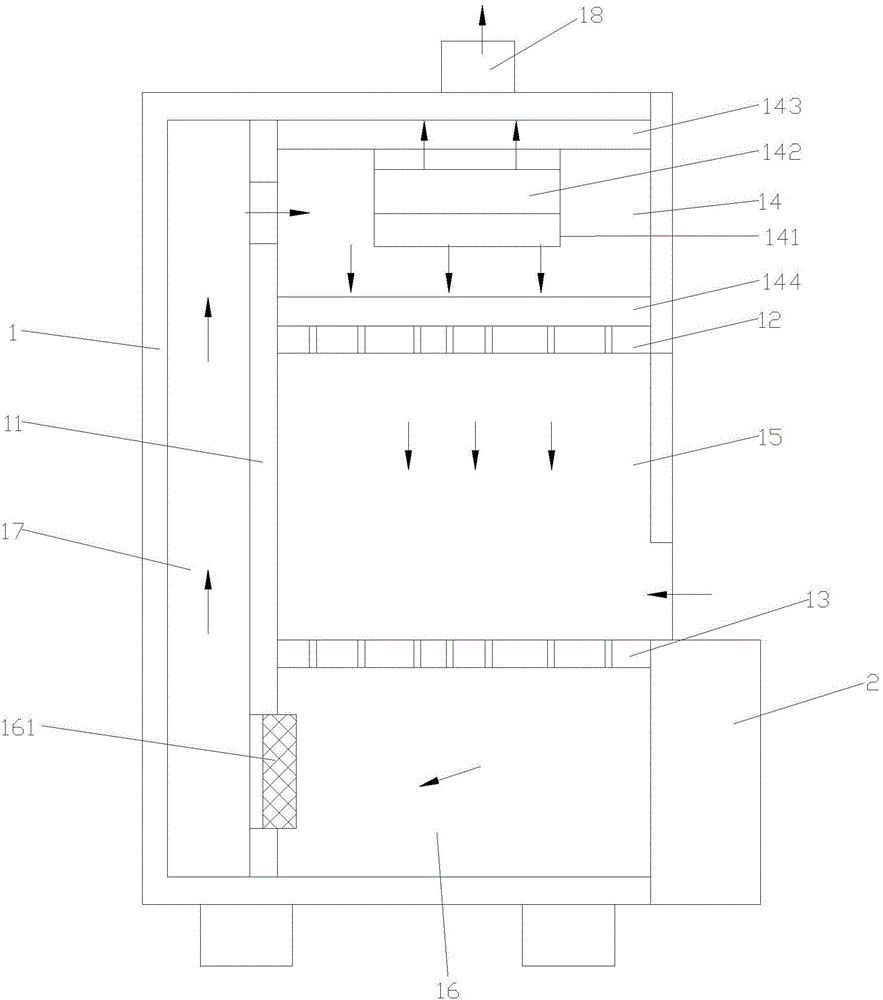
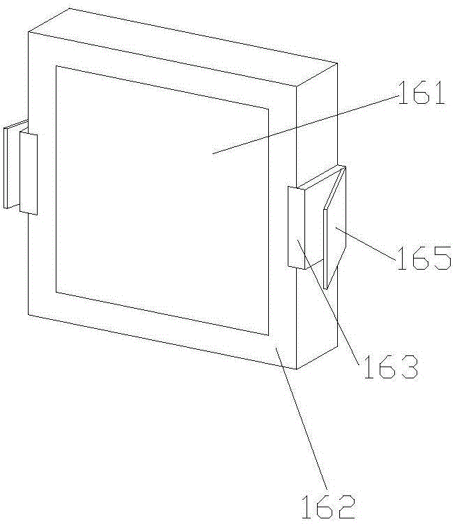
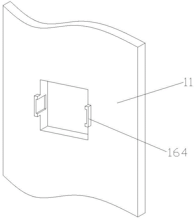
[0014] Such as figure 1 , figure 2 , image 3 as shown, figure 1 It is a structural representation of a CIT disinfection type biological safety cabinet proposed by the present invention; figure 2 It is a structural schematic diagram of an electrostatic dust accumulation device in a CIT disinfection type biological safety cabinet proposed by the present invention; image 3 It is a schematic diagram of the connection structure between the riser and the electrostatic precipitating device in a CIT disinfection type biological safety cabinet proposed by the present invention.

[0015] refer to figure 1 , figure 2 , image 3 , a kind of CIT disinfection type biosafety cabinet that the present invention proposes, comprises cabinet body 1, and cabinet body 1 inner rear side is provided with vertical partition 11 and cabinet body is divided into front cavity and back cavity, and front cavity is provided with parallel setting The upper diaphragm 12 and the lower diaphragm 13 d...


PUM


Abstract

The invention discloses a CIT disinfection type biological safety cabinet. The CIT disinfection type biological safety cabinet comprises a cabinet body, wherein the rear inner side of the cabinet body is provided with a vertical separation plate and the vertical separation plate is used for dividing the cabinet body into a front chamber and a rear chamber; the front chamber is internally provided with an upper transverse separation plate and a lower transverse separation plate which are used for dividing the front chamber into a static pressure chamber at the upper part, a working chamber in the middle and an electrostatic dust removing chamber at the lower part; the upper transverse separation plate and the lower transverse separation plate are both provided with first through holes for communicating the static pressure chamber and the electrostatic dust removing chamber with the working chamber; the working chamber is sealed by a glass protection window; vertical separation plates of the static pressure chamber and the electrostatic dust removing chamber are provided with second through holes communicated with the rear chamber; an air returning channel communicating the static pressure chamber with the electrostatic dust removing chamber is formed by the rear chamber; an electrostatic dust deposition device is mounted on the second through hole in the electrostatic dust removing chamber; the electrostatic dust deposition device is movably mounted on the corresponding vertical separation plate; and the cabinet body is provided with a cabinet door for sealing the electrostatic dust removing chamber. The CIT disinfection type biological safety cabinet has a simple structure; the filtering rate of a filtering film is improved and the service life of the filtering film is prolonged; and the danger in a maintaining process is reduced.

Description

technical field [0001] The invention relates to the technical field of biological safety cabinets, in particular to a CIT disinfection type biological safety cabinet. Background technique [0002] The biological safety cabinet is the main physical isolation equipment in the laboratory. It is designed to prevent the infectious aerosol generated during the laboratory operation from causing harm to the laboratory operators, prevent cross-contamination of laboratory items, and prevent the spread of harmful substances. [0003] Existing biological safety cabinets mainly use high-efficiency filter membranes to remove dust and bacteria from the air. The high-efficiency filter membranes use the inertia and diffusivity of dust particles, as well as the van der Waals force between particles and fibers, but the high-efficiency filter membranes are easy to clog and do not have The function of killing bacteria, after being filtered out, the bacteria will accumulate on the high-efficiency...

Claims


Application Information

Patent Timeline
IPC IPC(8): B01L1/00
Inventor 盛义良涂修章
Owner ANHUI HUASHENG TECH HLDG
Why Eureka
Try Eureka