
Dust collection device

A technology of dust removal device and pipeline, which is applied in the separation of dispersed particles, chemical instruments and methods, and filtration of dispersed particles, etc., which can solve the problems of smoke and dust polluting the atmosphere, affecting the effect of dust removal, and failure of the filter bag filter function.

Inactive Publication Date: 2015-04-29
常州市海伦工具有限公司
View PDF0 Cites 0 Cited by
  • Summary
  • Abstract
  • Description
  • Claims
  • Application Information

AI Technical Summary

Problems solved by technology

However, when the sand mold molded by resin sand is pouring and cooling, the riser of the sand mold will emit heavy smoke. Due to the roasting of high-temperature molten iron, the smoke components not only include smoke and carbon monoxide, but also produce a A resin volatile with a relatively high viscosity - tetrahydroenzyme (its viscosity can reach 30mPa.s at 20°C), when mixed with smoke, it will produce highly viscous and flammable black greasy particles, very It is easy to stick to the pipe wall of the ventilation and dust removal pipe and the filter bag of the bag filter. After a long time, the resistance of the filter bag will increase until it is blocked, resulting in the failure of the filter function of the filter bag and seriously affecting the dust removal effect.
Therefore, at present, in the resin sand molding production line in the domestic foundry industry, the flue gas from the pouring section and the cooling section is generally exhausted directly by fans without installing a dust collector. The "National Standard of the People's Republic of China - Air Pollutant Emission Standards for Foundry Industry" stipulates that the emission concentration limit of the pouring and cooling sections of newly-built enterprises is 30mg / m 3

Method used


Image

  • Dust collection device

Examples


Embodiment Construction

[0012] The present invention will be further described in detail below in conjunction with the accompanying drawings and specific embodiments.

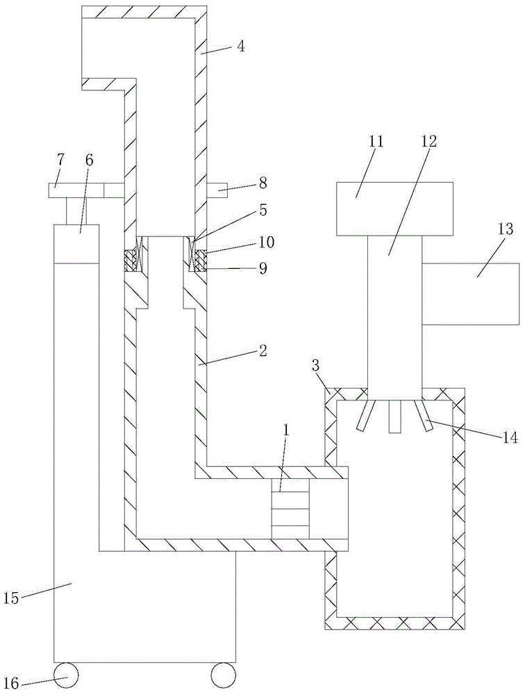
[0013] refer to figure 1 , a dust removal device of the present invention includes a fan 1, a pipeline 2, a cloth bag 3, a powder storage 11, a screw conveyor 12 and a pressure fan 13. The fan 1 is assembled in the pipeline 2, and the cloth bag 3 is connected with one end of the pipeline 2, and the section of the pipeline 2 is L-shaped. The powder storage 11 is connected to one end of the screw conveyor 12, and the other end of the screw conveyor 12 extends into the cloth bag 3, and the pressure fan 13 is connected to the screw conveyor 12, and the screw conveyor 12 extends into the cloth bag A plurality of sprinkler heads 14 are provided at the end of the wall. It also includes an air intake device and a driving device, the air intake device includes an L-shaped air intake pipe 4 and a bearing 5, the bearing 5 is fixed in the air i...


PUM


Abstract

The invention relates to a dust collection device which comprises a fan, a pipeline, a bag, a powder storage device, a screw conveyor and a pressure fan, wherein the fan is assembled in the pipeline, the bag is connected with one end of the pipeline, the powder storage device is connected with one end of the screw conveyor, the other end of the screw conveyor extends into the bag, and the pressure fan is connected with the screw conveyor; the dust collection device further comprises an air inlet device and a driving device; the air inlet device comprises an L-shaped air inlet pipe and a bearing which is fixed in the air inlet pipe, and an end part of the pipeline is fixedly connected with an inner ring of the bearing; the driving device comprises a driving motor, a driving gear and a driven gear, an shaft output end of the driving motor is fixedly connected with the driving gear, and the driven gear is fixed on the outer wall surface of the pipeline, and the driven gear is meshed with the driving gear. The dust collection device can prevent dust particles from being contacted or bonded with the bag and can absorb airflow in a workshop environment comprehensively, so that smoke in the airflow can be removed.

Description

technical field [0001] The invention relates to a dust removal device. Background technique [0002] With the development and improvement of casting technology, no-hardening resin and phenolic resin sand molding have been widely used in my country's foundry industry, which not only shortens the production cycle, improves production efficiency, but also improves the appearance quality of castings. However, when the sand mold molded by resin sand is pouring and cooling, the riser of the sand mold will emit heavy smoke. Due to the roasting of high-temperature molten iron, the smoke components not only include smoke and carbon monoxide, but also produce a A resin volatile with a relatively high viscosity - tetrahydroenzyme (its viscosity can reach 30mPa.s at 20°C), when mixed with smoke, it will produce highly viscous and flammable black greasy particles, very It is easy to stick to the pipe wall of the ventilation and dust removal pipe and the filter bag of the bag filter. Ove...

Claims


Application Information

Patent Timeline
IPC IPC(8): B01D46/02B01D46/42
Inventor 曹大龙
Owner 常州市海伦工具有限公司
Learn More