Limit mechanism of needle holder in retraction type safety syringe
A technology of a safety syringe and a limiting mechanism, which is applied to hypodermic injection devices, needles, medicine devices, etc., can solve the problems of high assembly cost, unstable structure, and inability to form annular protrusions.
- Summary
- Abstract
- Description
- Claims
- Application Information
AI Technical Summary
Problems solved by technology
Method used
Image

Examples
Embodiment 1
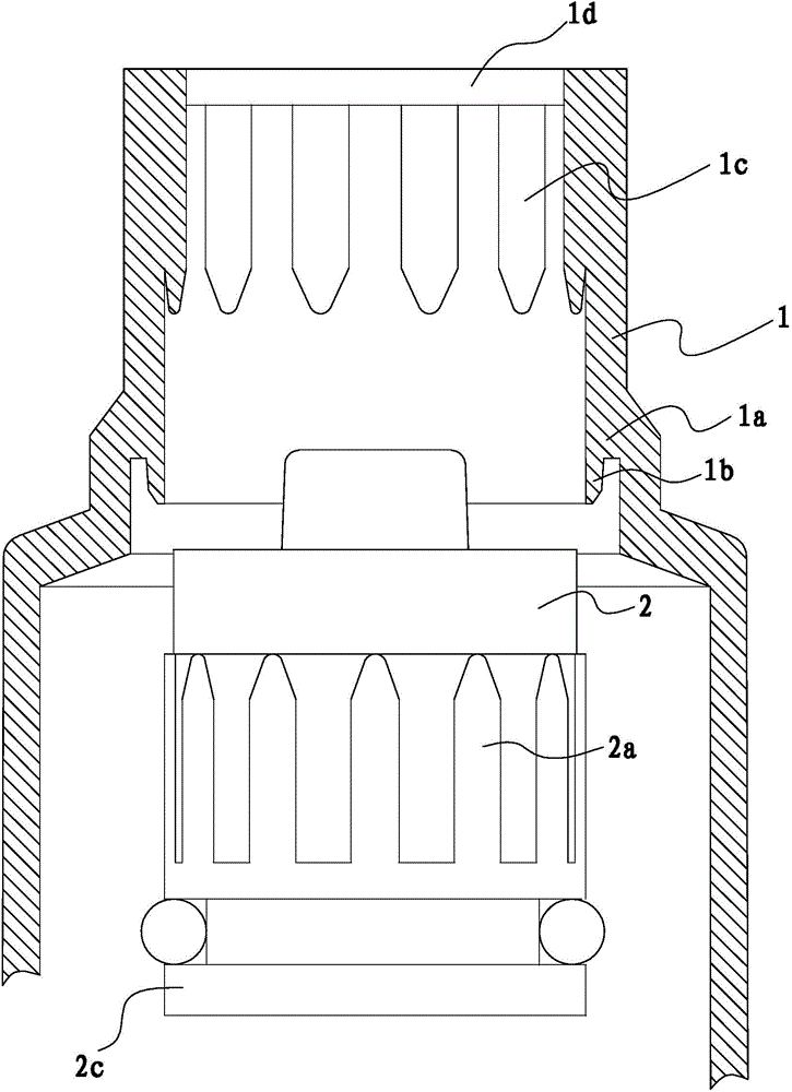
[0030] Such as Figure 5 As shown, the syringe includes a syringe 1 and a cylindrical needle holder 2 fixed on the inner side of the upper end of the syringe 1. The inner side of the needle holder 2 has an annular protrusion-2b. During use, the needle head 4 is fixed on the needle seat 2, and a push rod 5 is arranged in the needle cylinder 1.
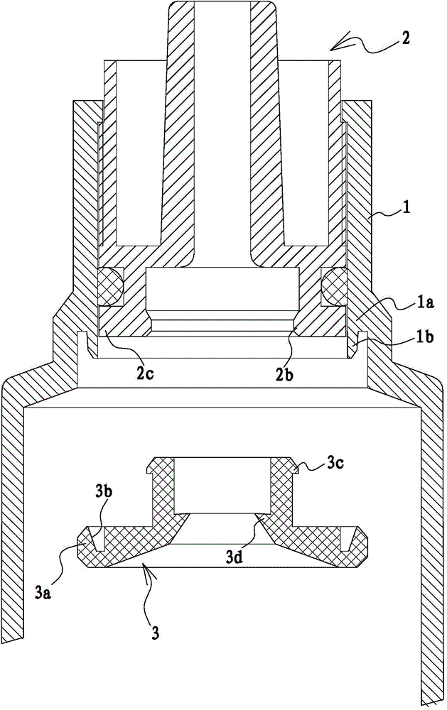
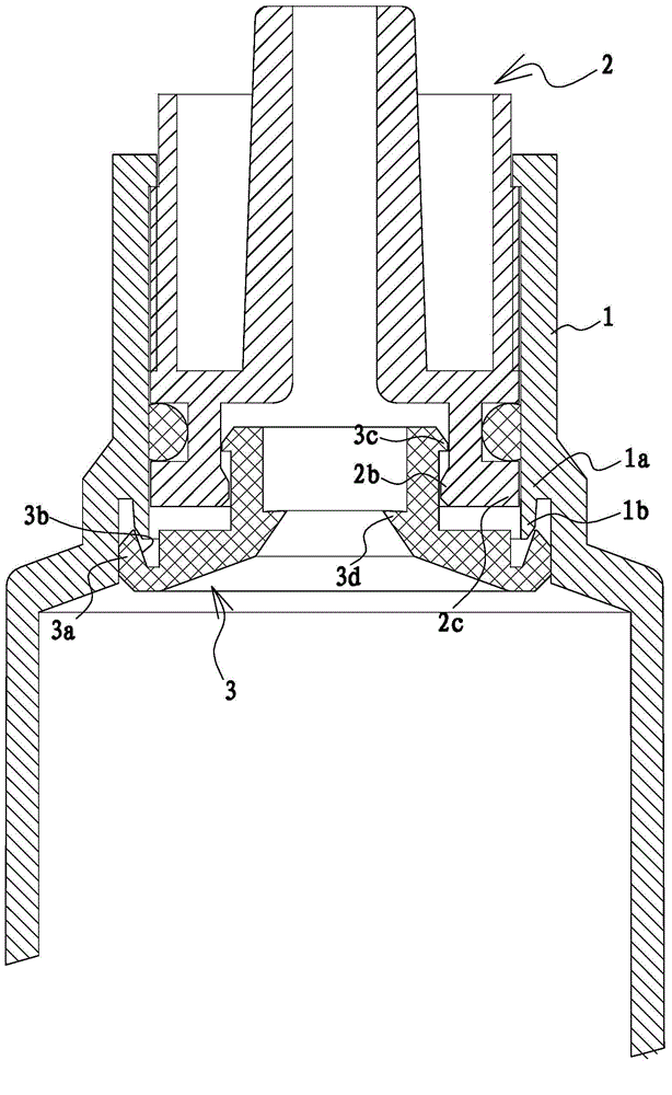
[0031] Such as Figure 4 As shown, in the retractable safety syringe, the stop mechanism between the needle holder and the needle cylinder is arranged between the needle cylinder 1 and the needle holder 2 .
[0032] In order to prevent the needle 4 from rotating or moving back and forth during use, there is a limiting unit 1 between the needle cylinder 1 and the needle holder 2 for limiting the upward movement of the needle holder 2, and between the needle cylinder 1 and the needle holder 2 there is a The limiting unit 2 restricts the downward movement of the needle base 2 , and a structure for preventing the needle base 2 from rotati...
Embodiment 2
[0048] This embodiment is similar to Embodiment 1, the difference is that in this embodiment, if Figure 10 and Figure 11 As shown, there is only one annular protrusion on the expander 3: annular protrusion three 3d; there are two annular protrusions on the push rod 5: annular protrusion five 5b and annular protrusion six 5c, the annular protrusion The fifth 5b is located on the upper side of the annular protrusion six 5c. When the syringe is used up, push the push rod 5 up to the bottom, the annular protrusion 5b on the push rod 5 crosses the annular protrusion 1 2b of the needle seat 2, and the annular protrusion 5c on the push rod 5 crosses the expansion The annular protrusion 3 3d of the piece 3. Thereafter, the push rod 5 is pulled back, and the annular protrusion 6 5c of the push rod 5 first abuts against the annular protrusion 3 3d of the expansion member 3 and drives the expansion member 3 to break away from the stopper 1b; after that, the push rod 5 The ring-shape...
Embodiment 3
[0050] This embodiment is similar to Embodiment 1, the difference is that in this embodiment, if Figure 12 As shown, the inner wall of the syringe 1 has a backstop protrusion 1e for preventing the expansion member 3 from moving down, and the backstop protrusion 1e is located on the lower side of the expansion part 3a and abuts against the expansion part 3a. As the specific shape of the anti-retreat protrusion 1e, the anti-retreat protrusion 1e can be set as a circular ring coaxial with the syringe 1, or can be set as a number of block-shaped anti-retreat protrusions evenly distributed on the inner wall of the syringe 1. from 1e. As another embodiment, the backstop protrusion 1e is used to prevent the needle holder 2 from moving down, and the backstop protrusion 1e abuts against the needle holder 2 . As another way, the anti-retreat protrusion can also be located on the expansion member, and there is an anti-retreat groove on the inner wall of the syringe that matches the sha...
PUM
 Abstract
Description
Claims
Application Information
 - R&D
- Intellectual Property
- Life Sciences
- Materials
- Tech Scout
- Unparalleled Data Quality
- Higher Quality Content
- 60% Fewer Hallucinations
Browse by: Latest US Patents, China's latest patents, Technical Efficacy Thesaurus, Application Domain, Technology Topic, Popular Technical Reports.
© 2025 PatSnap. All rights reserved.Legal|Privacy policy|Modern Slavery Act Transparency Statement|Sitemap|About US| Contact US: help@patsnap.com