
Numerical control variable-resistance device

A technology of standard resistance and digital-to-analog conversion circuit, which is applied in the direction of the resistance element adjusted by short-circuiting different numbers of resistance elements, which can solve the problems of large reading jump, weak anti-interference ability, limited range, etc., and achieve fast response speed , strong anti-interference ability, wide range of effects

Active Publication Date: 2015-04-22
浙江劲仪仪器仪表有限公司
View PDF4 Cites 2 Cited by
  • Summary
  • Abstract
  • Description
  • Claims
  • Application Information

AI Technical Summary

Problems solved by technology

However, there is a common problem in the current rheostat devices on the instrument: the existing rheostat devices generally need to add a current (voltage) source in the circuit to simulate the resistance characteristics. When simulating near zero resistance, the numerical control current (voltage) ) The source output is close to its upper limit value, affected by the stability characteristics of its internal electronic devices, the absolute value of the output signal fluctuation is larger than when it outputs a small signal, resulting in poor stability when simulating a small resistance value
In addition, when the output of the digital-to-analog conversion circuit of the existing rheostat is zero, the analog resistance output is not zero resistance, which results in fixed resolution and cannot simulate higher resolution in the range of small resistance values.
In addition, the existing varistors have weak anti-interference ability to high-frequency current noise on the external excitation current, and when the field equipment powered by switching power supply is used, the reading jumps greatly
Existing rheostats have a limited range of simulated resistance values ​​and cannot simulate resistance values ​​from 0 to infinity

Method used


Image

  • Numerical control variable-resistance device
  • Numerical control variable-resistance device
  • Numerical control variable-resistance device

Examples


Embodiment Construction

[0019] The technical solutions in the embodiments of the present invention will be clearly and completely described below in conjunction with the accompanying drawings in the embodiments of the present invention. Obviously, the described embodiments are only part of the embodiments of the present invention, not all of them. Based on the implementation manners in the present invention, all other implementation manners obtained by persons of ordinary skill in the art without making creative efforts belong to the protection scope of the present invention.

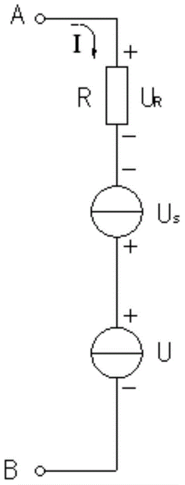
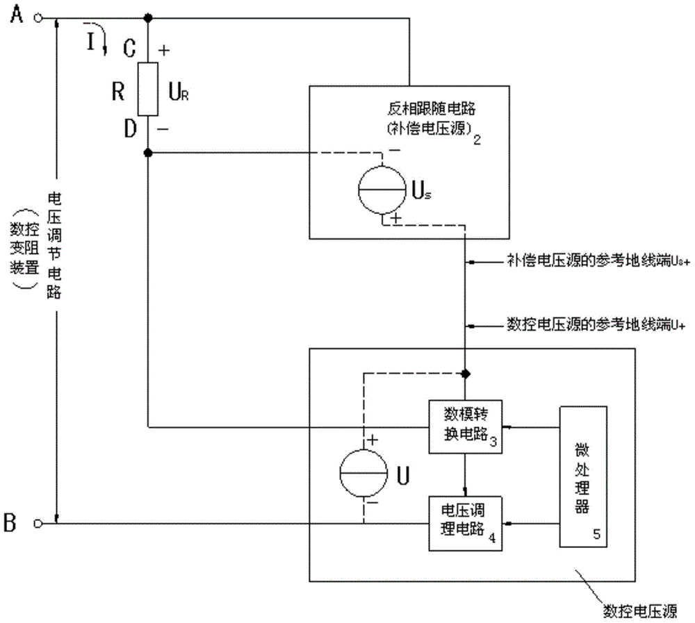
[0020] Please see attached figure 1 , The numerically controlled rheostat device of the present invention includes: a first port A and a second port B, and a voltage regulation circuit connected between the two ports.

[0021] The voltage regulation circuit includes: a standard resistance R, a compensation voltage source U that tracks the voltage on the standard resistance R S And a digitally controlled voltage source U with ...


PUM


Abstract

The invention provides a numerical control variable-resistance device. The numerical control variable-resistance device comprises a first port A, a second port B and a voltage adjusting circuit connected between the first port A and the second port B. The voltage adjusting circuit comprises a standard resistor R, an offset voltage source US and a numerical control voltage source U with the variable output voltage. The offset voltage source US is used for offsetting voltage drop at the two ends of the standard resistor R through a reversal-phase follow circuit (2), wherein one end C of the standard resistor R is connected with the first port A, and the other end D of the standard resistor R is connected with the output end US- of the offset voltage source; the reference ground wire end US+ of the offset voltage source US is connected with the reference ground wire end U+ of the numerical control voltage source U; the output end U- of the numerical control voltage source is connected with the second port B; the output end US- of the offset voltage source US is connected with the reference input end of a digital-to-analogue conversion circuit (3) in the numerical control voltage source to provide the reference end voltage for the numerical control voltage source. The numerical control variable-resistance device has the advantages that the simulation output resistance is stable, the definition is adjustable, and the simulation resistance scope is wide.

Description

technical field [0001] The invention relates to the technical field of industrial control, in particular to a numerically controlled rheostat device. Background technique [0002] With the development of electronic technology, in the field of industrial process control calibration, more and more instruments use numerical control rheostat design to facilitate the application. However, there is a common problem in the current rheostat devices on the instrument: the existing rheostat devices generally need to add a current (voltage) source in the circuit to simulate the resistance characteristics. When simulating near zero resistance, the numerical control current (voltage) ) source output is close to its upper limit value, affected by the stability characteristics of its internal electronic devices, the absolute value of the output signal fluctuation is larger than when it outputs a small signal, resulting in poor stability when simulating a small resistance value. In additio...

Claims


Application Information

Patent Timeline
IPC IPC(8): H01C10/06
Inventor 姚治贡何银锋袁勇业
Owner 浙江劲仪仪器仪表有限公司
Learn More