
Optical fiber corner reserving frame

A technology of optical fiber and angle, which is applied in the field of optical fiber and can solve the problems of reduced optical fiber life

Inactive Publication Date: 2015-04-22
STATE GRID CORP OF CHINA +1
View PDF7 Cites 1 Cited by
  • Summary
  • Abstract
  • Description
  • Claims
  • Application Information

AI Technical Summary

Problems solved by technology

[0004] The main purpose of the present invention is to provide a kind of optical fiber corner reservation rack, to solve the problem of reducing the life of the optical fiber caused by reserving the margin of the optical fiber corner in the prior art

Method used


Image

  • Optical fiber corner reserving frame
  • Optical fiber corner reserving frame

Examples


Embodiment Construction

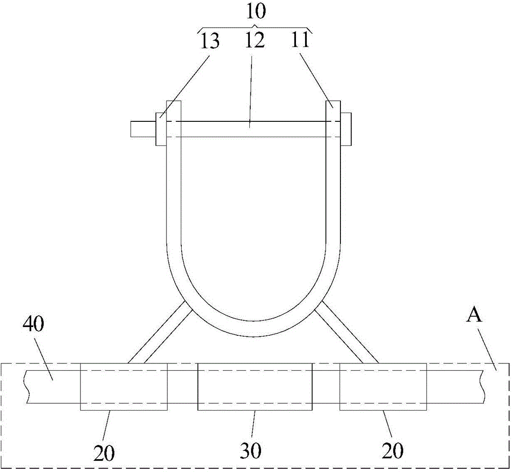
[0020] It should be noted that, in the case of no conflict, the embodiments of the present invention and the features in the embodiments can be combined with each other. The present invention will be described in detail below with reference to the accompanying drawings and examples.

[0021] In order to enable those skilled in the art to better understand the solutions of the present invention, the following will clearly and completely describe the technical solutions in the embodiments of the present invention in conjunction with the drawings in the embodiments of the present invention. Obviously, the described embodiments are only It is an embodiment of a part of the present invention, but not all embodiments. Based on the embodiments of the present invention, all other embodiments obtained by persons of ordinary skill in the art without making creative efforts shall fall within the protection scope of the present invention.

[0022] Such as figure 1 and figure 2 As show...


PUM


Abstract

The invention provides an optical fiber corner reserving frame. The optical fiber corner reserving frame comprises a wire pole fixing element (10) which is fixedly connected with a wire pole, two optical fiber clamping parts (20) which are arranged on a wire pole fixing frame, and a reserved optical fiber protecting part (30), wherein a corner allowance space of a reserved optical fiber (40) is reserved between the two optical fiber clamping parts (20), a curved channel for the optical fiber to pass is arranged in the reserved optical fiber protecting part (30), and the reserved optical fiber (40) is sleeved with the reserved optical fiber protecting part (30). Due to the technical scheme of the optical fiber corner reserving frame, the problem that the service life of an optical fiber is shortened because of reserved optical fiber corner allowance in the prior art is effectively solved.

Description

technical field [0001] The invention relates to the field of optical fiber technology, in particular to an optical fiber corner reserved frame. Background technique [0002] During the laying process of aerial optical cables, the optical fiber cables at the corners of the poles need to reserve a margin of optical fiber corners to prevent thermal expansion and contraction from damaging the optical fibers. The existing method for reserving the corner margin of the optical fiber is to fix a section of optical fiber through two fixed points, and bend a section of optical fiber between the two fixed points. [0003] However, this method is very difficult to control the curvature radius of the bent optical fiber. If the curvature radius is too small, it is likely to affect the communication quality of the optical fiber and the life of the optical fiber. In addition, the bent optical fiber will continue to rub against the wire rod under the action of natural factors, resulting in ...

Claims


Application Information

Patent Timeline
Patent Type & Authority Applications(China)
IPC IPC(8): G02B6/44
CPCG02B6/444G02B6/4452
Inventor 张涛
Owner STATE GRID CORP OF CHINA
Learn More