
A gas pedal structure

An accelerator pedal and right side plate technology, applied in the field of auto parts, can solve the problems of large pedal movement space and long acceleration time of the car, and achieve the effect of convenient compact layout and short acceleration time

Active Publication Date: 2016-11-02
ANHUI JIANGHUAI AUTOMOBILE GRP CORP LTD
View PDF5 Cites 0 Cited by
  • Summary
  • Abstract
  • Description
  • Claims
  • Application Information

AI Technical Summary

Problems solved by technology

[0004] The purpose of the present invention is to provide an accelerator pedal structure to solve the problems of relatively large movement space of the pedal and long acceleration time of the automobile in the prior art

Method used


Image

  • A gas pedal structure
  • A gas pedal structure
  • A gas pedal structure

Examples


Embodiment Construction

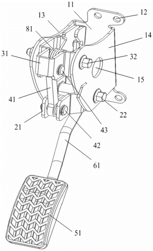
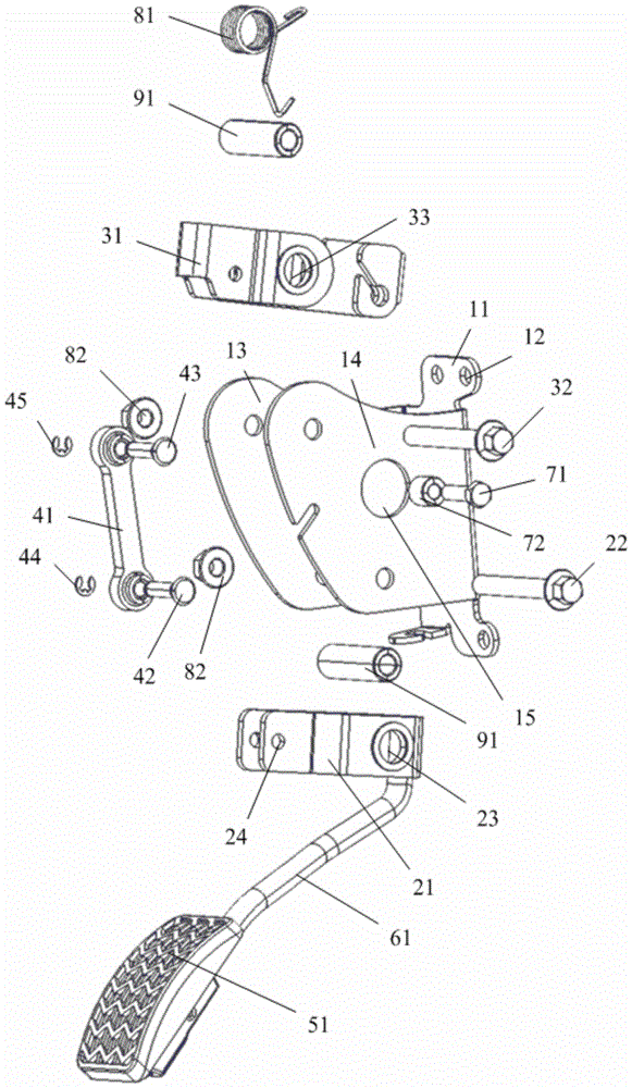
[0026] Such as Figure 1 to Figure 6 As shown, the embodiment of the present invention provides an accelerator pedal structure, which includes a first support 21, a second support 31, a fixed arm 61 fixedly connected to the pedal 51, and a mounting seat connected to the vehicle body. Wherein, the first support 21 is provided with a first mounting part that is rotatably connected to the lower end of the mounting seat, and the side of the first support 21 close to the first mounting part is fixedly connected with the other end of the fixed arm 61. The first support The side away from the first mounting portion on the seat 21 is rotationally connected with the lower end of the connector; the second mounting portion 31 is provided with a second mounting portion which is rotationally connected with the upper end of the mounting base, and the second mounting portion is close to the second mounting portion on the second mounting portion 31. One side of the part is rotatably connected...


PUM


Abstract

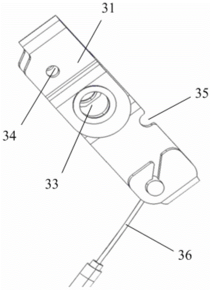
The invention provides an accelerator pedal structure. The accelerator pedal structure comprises a first supporting seat, a second supporting seat, a fixing arm fixedly connected with a pedal and an installing seat connected with a car body. The first supporting seat is provided with a first installing part which is rotatably connected with the lower end of the installing seat. One side, close to the first installing part, of the first supporting seat is fixedly connected with the other end of the fixing arm. One side, far away from the first installing part, of the first supporting seat is rotatably connected with the lower end of a connecting part. The second supporting seat is provided with a second installing part rotatably connected with the upper end of the installing seat. One side, close to the second installing part, of the second supporting seat is rotatably connected with the upper end of the connecting part. One side, far away from the second installing part, of the second supporting seat is connected with an accelerator drawing wire. The second supporting seat is provided with a return device. According to the accelerator pedal structure, the movement space of the pedal is small, and the acceleration time of a car is short.

Description

technical field [0001] The invention relates to the technical field of auto parts, in particular to an accelerator pedal structure. Background technique [0002] As one of the important control units of the vehicle, the accelerator pedal on the car has an irreplaceable function. The driver controls the angle of the accelerator pedal through the foot, so that the opening of the engine throttle changes, and then realizes the control of the vehicle speed. . [0003] The existing accelerator pedal structure generally includes a pedal and a pedal arm, wherein the pedal arm is rotatably connected to the support through a pin shaft, one end of the pedal arm is fixedly connected to the pedal, the other end of the pedal arm is connected to the accelerator wire, and the other end of the accelerator wire is connected to the joint. The valves are connected. At this time, the angle of the pedal is the same as the opening of the throttle valve. The angle of the pedal is the angle at whi...

Claims


Application Information

Patent Timeline
Patent Type & Authority Patents(China)
IPC IPC(8): B60K26/02
Inventor 李盈盈余志华胡杰刘聪聪张伟吴昌庆杨东升刘韶雷马骁宇
Owner ANHUI JIANGHUAI AUTOMOBILE GRP CORP LTD
Learn More