
Skin tag removal system

a skin tag and removal system technology, applied in the field of skin tag removal, can solve the problems of skin tags that interfere with shaving and other grooming rituals, waste of medical personnel and resources, and high cost, and achieve the effect of facilitating the application of compressive force or pressure, reducing or restricting the blood flow required to sustain the skin tag

Inactive Publication Date: 2010-05-06
ROTUNDA ADAM
View PDF7 Cites 25 Cited by
  • Summary
  • Abstract
  • Description
  • Claims
  • Application Information

AI Technical Summary

Benefits of technology

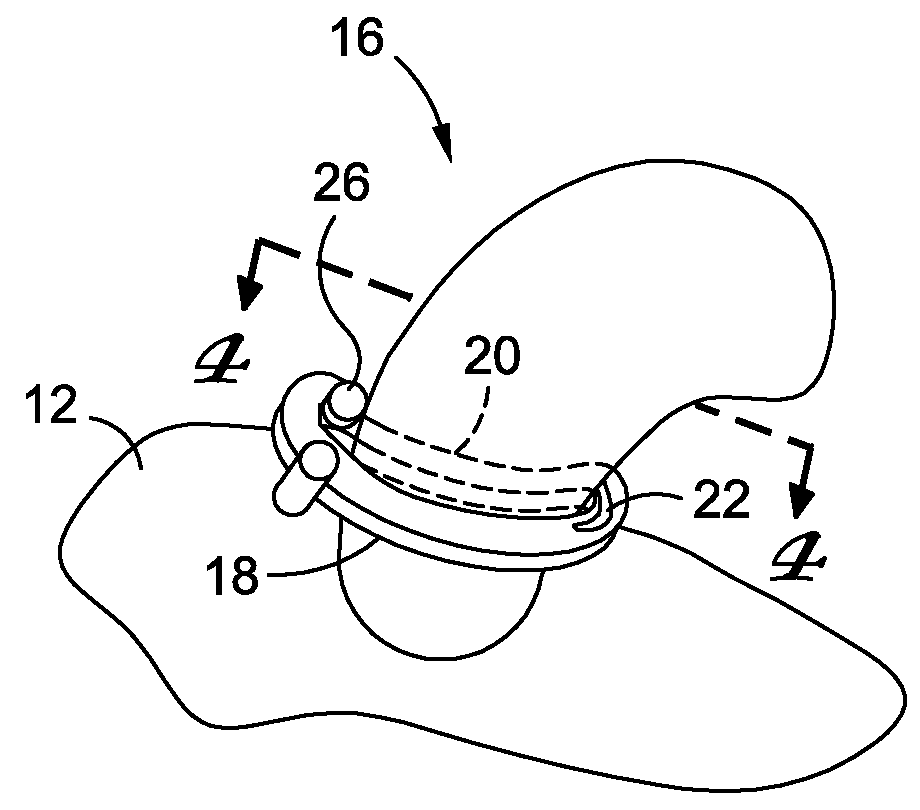
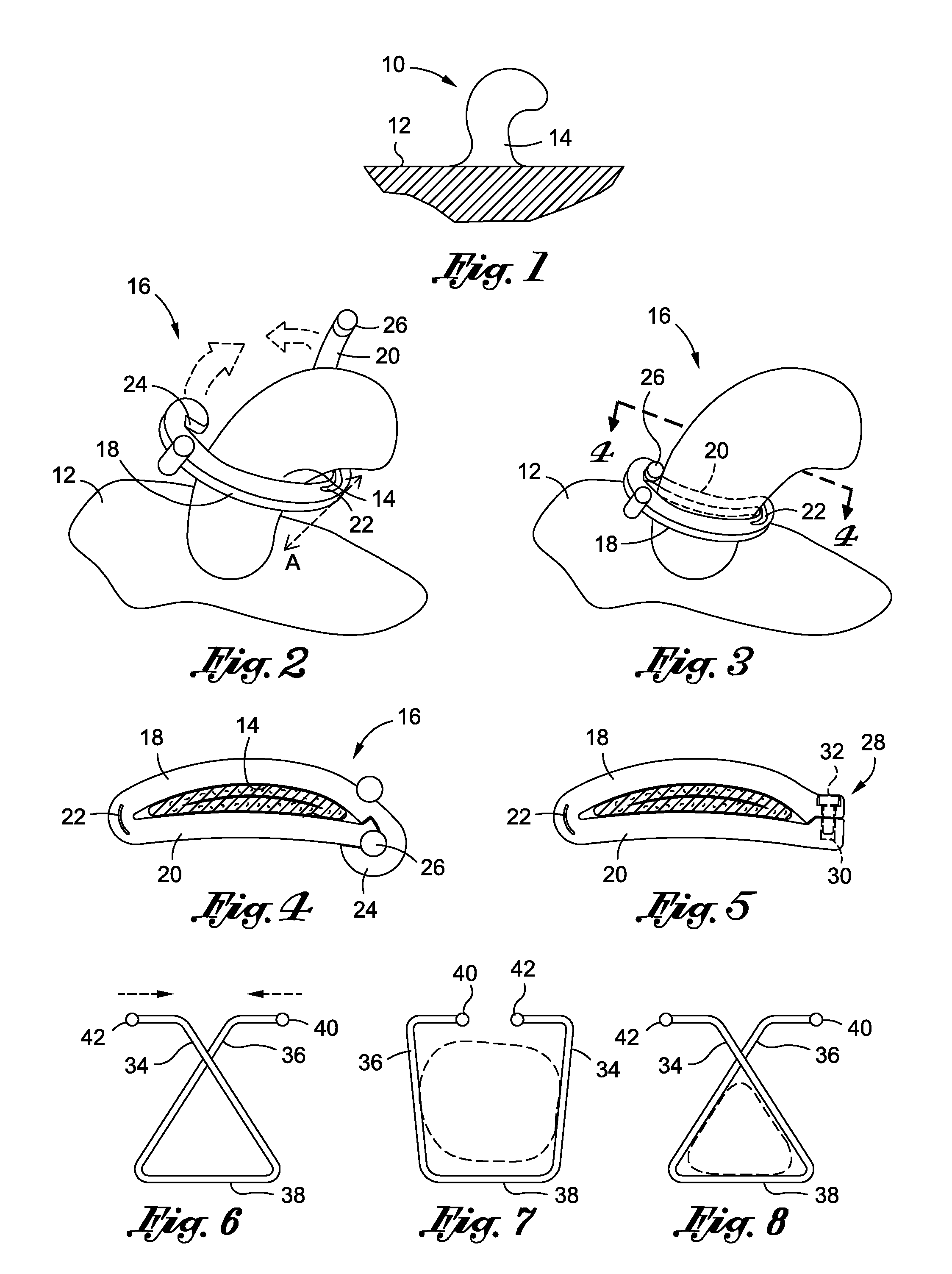
[0011]In a first embodiment, the skin tag removal device comprises first and second elongate members connected to one another via a hinge and are operatively transitionable between a first open configuration whereby the first and second elongate members may be separated from one another, and a second compressive configuration whereby the first and second elongate members are caused to compress inwardly toward one another. To that end, the first and second members may be joined by a living hinge that biases the first and second members inwardly toward one another, or may otherwise be joined by a joint, pivot or other similar-type mechanism that enables the first and second members to operatively transition between the first and second configurations.
[0012]When the clip of the skin tag removal device is oriented in the open position, the first and the second member may be placed in close proximity to the base of the skin tag. In other words, the open position of the clip enables the base of the skin tag to be received. The opening between the first member and the second member associated with the open position may be adjusted in accordance with the size of the skin tag. Because both the first member and the second member are movable relative to each other, the skin tag removal device may accommodate skin tags of many different shapes and sizes by moving either the first member or the second member accordingly. When in the open position, the first member and the second member may form an opening similar to an open jaw for the base of the skin tag to be received. From the open position, the first member and the second member may move toward each other to steadily decreasing the opening between the first member and the second member, resembling a closing scissor. The opening may decrease until the closed position is achieved. As the first member and the second member move closer to each other a compressive force is imparted onto the base of the skin tag. The compressive force stops reduces the blood flow to the skin tag by reducing circulation at the base of the skin tag.
[0013]As discussed above, the first member and the second member may be joined to one another by a hinge. The hinge may facilitate the pivotal movement of the first member relative to the second member. The hinge may also facilitate the pivotal movement of the second member relative to the first member. As a result, the hinge connecting the first member and the second member enables the clip to transition between the open and closed positions. The hinge may further define a fixed axis of rotation and both the first member and the second member may be capable of rotating about the fixed axis of motion. The rotation of the first member and the second member relative to the fixed axis of rotation allows for the opening to be increased or decreased dependent upon whether the clip is to be oriented in the open or closed position. To remove the skin tag, the first member and the second member may move to the open position. Depending on the size of the skin tag and in particular the base of the skin tag, the opening between the first and second members may be adjusted to receive the base of the skin tag. Subsequent to receiving the base of the skin tag, the first member and the second member may move toward each other causing the opening between the two members to decrease whereby the opening is reduced until the closed position is attained. As the opening between the two members is reduced, the compressive force applied to the base of the skin tag is increased until the closed position between the first member and the second member is achieved.
[0014]In the closed clip position, the first member and the second member of the skin tag removal device may be secured to each other such that the closed position may be maintained until the necrotic skin tag is released from the skin surface to which it was attached. To maintain the closed position between the first member and the second member of the skin tag removal device a mechanical fastener may be used. Preferably, the mechanical fastener used to secure the ends of the first member and the second member is located opposite the hinge at which the first and second members are joined such that when the first member and the second member are locked together the application of compressive force from the clip to the base of the skin tag is maintained. This allows for removal of the skin tag following a brief period of time in which the first member and the second member cooperate to impart a compressive force to stop or substantially reduce blood flow to the skin tag.

Problems solved by technology

Although skin tags are harmless, they are frequently removed, usually for cosmetic reasons or due to irritation caused by contact with clothing or jewelry.
Skin tags may also interfere with shaving and other grooming rituals.
Visiting a doctor's office for such a minor procedure involving a harmless skin condition, however, may be costly, time consuming and is otherwise a wasteful use of medical personnel and resources.
Lacking sufficient blood flow, the living tissue in the skin tag quickly recedes and falls off spontaneously.
However, some of these methods that allow individuals to remove their skin tags may be difficult to use, expensive, or slow.
In addition, individuals seeking to remove skin tags on their own may unnecessarily hurt themselves and cause damage to surrounding areas of the skin due to incompetent or unreliable deployment of a skin tag removal modality.

Method used


Image

  • Skin tag removal system
  • Skin tag removal system

Examples


Embodiment Construction

[0027]The above description is given by way of example, and not limitation. Given the above disclosure, one skilled in the art could devise variations that are within the scope and spirit of the invention disclosed herein, including various ways of devising a skin tag removal device configured to be oriented in a closed position and an open position. Further, the various features of the embodiments disclosed herein can be used alone, or in varying combinations with each other and are not intended to be limited to the specific combination described herein. Thus, the scope of the claims is not to be limited by the illustrated embodiments.

[0028]The device of the present invention allows for the removal of skin tags using a pair of members used to press against the base of the skin tag to reduce or restrict the blood flow to the skin tag. The different components form part of a device which may be placed adjacent to the skin, and in particular around a base of the skin tag to thus cut o...


PUM


Abstract

A skin tag removal device operative to remove skin tags via the use of compressive force to stop or restrict blood flow to the skin tag. The device comprises first and second members that are attached to one another, preferably via a hinge, and operative to assume an open configuration whereby the members may be positioned about the base of a skin tag and a second closed configuration whereby the first and second members cooperate to impart a compressive force about the base of the skin tag to stop or substantially restrict blood flow. The first and second members may be formed such that the same are biased to one another to impart the compressive force, or may be attached via a hinge and operative to be locked to one another to assume the closed, blood-restricting configuration.

Description

CROSS-REFERENCE TO RELATED APPLICATIONS[0001]Not ApplicableSTATEMENT RE: FEDERALLY SPONSORED RESEARCH / DEVELOPMENT[0002]Not ApplicableBACKGROUND[0003]1. Technical Field of the Invention[0004]The present invention relates generally to a device for removing skin tags protruding from an area of skin and, more particularly, to a skin tag removal device for imparting a compressive force to the base of the skin tag to reduce and / or restrict blood flow to the skin tag for a period of time sufficient to cause necrosis and removal of the skin tag.[0005]2. Description of the Related Art[0006]Skin tags, also known as acrochordons, are small benign tumors that form on an area of skin. Typically, the skin tag protrudes from the skin surface as a bulbous skin mass, and may appear throughout the body including the neck, armpit, groin, face, eyelids. Skin tags vary in size but are usually between 1 mm and 5 cm. The surface of the skin tag may be smooth or irregular in appearance, and often the skin ...

Claims


Application Information

Patent Timeline
Patent Type & Authority Applications(United States)
IPC IPC(8): A61B17/08
CPCA61B17/083A61B2017/00747
Inventor ROTUNDA, ADAM
Owner ROTUNDA ADAM
Learn More