Ka-waveband cavity coupling feed circular polarized horn antenna

A horn antenna, circular polarization technology, applied in waveguide horns, antennas, antenna arrays, etc., can solve problems such as limiting tracking speed and reducing angular tracking accuracy, achieving high query accuracy, cost and space savings, and high anti-interference ability. Effect

Inactive Publication Date: 2015-04-15
UNIV OF ELECTRONICS SCI & TECH OF CHINA
View PDF2 Cites 14 Cited by
  • Summary
  • Abstract
  • Description
  • Claims
  • Application Information

AI Technical Summary

Problems solved by technology

Because the conical scanning antenna system adopts the sequential comparison lobe method, the direction of the target can only be determined after the feed source rotates around the antenna axis for this system, which limits the trackin...

Method used


Image

  • Ka-waveband cavity coupling feed circular polarized horn antenna
  • Ka-waveband cavity coupling feed circular polarized horn antenna
  • Ka-waveband cavity coupling feed circular polarized horn antenna

Examples


Embodiment Construction

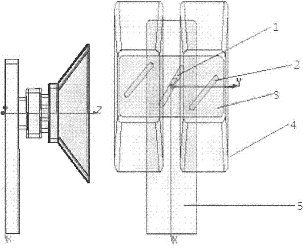
[0037] figure 1 Specific embodiments of the invention are described. according to figure 1 As shown, the unit of this antenna array includes a feed slant slot (1) a coupling slant slot (2) a coupling cavity (3), two pyramid horns (4), a feed waveguide (5), and one end of the waveguide as an input , open oblique slots on the center line of the waveguide top surface to couple energy to the cavity, and open oblique slots along the center line of the wide side of the cavity and on both symmetrical sides of the central oblique slot to feed the horn. The pyramid horn and the above components can also be made of other metal materials, and the use of other materials to make the antenna should certainly belong to the scope of the present invention.

[0038] The size of the rectangular waveguide of the pyramid horn antenna is 4.4×5.69×1mm3, and the diameter of the horn is 6×15.5×3.5mm3. The wall thickness is 1mm. The connection design of the feed waveguide and the coupling cavity is ...


PUM


Abstract

The invention relates to a cavity coupling slot excited circular polarized horn antenna comprising a feed inclined slot (1), a coupling inclined slot (2), a coupling cavity (3), two pyramid horns (4) and feed waveguide (5). The coupling cavity is slotted by adopting coupling waveguide and then double slots are slotted on the coupling cavity for horn feed, wherein the coupling waveguide is internally provided with an adjusting column for adjusting impedance matching. Integration of the horn antenna and a circular polarized feed source is realized by the design. Electrical performance of the cavity coupling feed circular polarized pyramid horn antenna is not quite different from that of a previous wide-brimmed center inclined slot feed circular polarized horn antenna, and advantages are that the network is relatively simple, the feed structure after arraying is more compact and the tail end of a power dividing network is only provided with 14 ports. Now most of interrogation antennas are micro-strip antennas working in the L-waveband. The micro-strip antennas are liable to be affect by electromagnetic interference of the same frequency band, and the micro-strip type antennas also have the disadvantage of lower gain. The circular polarized horn antenna works in the Ka-waveband so that the characteristic of high gain of the horn antenna can be retained, circular polarization can also be realized, and thus the circular polarized horn antenna can act as an ideal mono-pulse antenna.

Description

technical field [0001] The invention belongs to the technical field of antenna engineering, in particular to a Ka-band millimeter-wave interrogation antenna. Background technique [0002] With the development of rockets, artificial satellites and aerospace technology, higher requirements are put forward for the tracking speed, tracking accuracy, tracking distance and anti-interference ability of tracking radar. Since the conical scanning antenna system adopts the sequential comparison lobe method, the direction of the target can only be determined after the feed source rotates around the antenna axis for this system, which limits the tracking speed; during the beam scanning process, the change of the target motion state causes The fluctuation of the echo signal amplitude adds an amplitude modulation interference to the error signal, and also reduces the angle tracking accuracy. The monopulse system adopts the method of comparing lobes at the same time, which can obtain the ...

Claims


Application Information

Patent Timeline
IPC IPC(8): H01Q13/02H01Q13/04H01Q21/00
Inventor 邵凯王建张宁黄懈周增广
Owner UNIV OF ELECTRONICS SCI & TECH OF CHINA
Why Eureka
Try Eureka