
Ultrasonic transducer driving power supply

A technology for driving power supply and transducer, applied in the direction of instruments, simulators, computer control, etc., can solve problems such as affecting welding quality and reducing energy conversion efficiency of transducers, and achieve the effect of improving bonding quality and efficiency.

Inactive Publication Date: 2015-04-15
CETC BEIJING ELECTRONICS EQUIP
View PDF5 Cites 16 Cited by
  • Summary
  • Abstract
  • Description
  • Claims
  • Application Information

AI Technical Summary

Problems solved by technology

Ultrasonic transducers have the highest conversion efficiency of mechanical energy when they reach resonance, but the resonance frequency will drift within a certain range due to various mechanical installation and load factors, which will directly lead to a decrease in the energy conversion efficiency of the transducer, thus affecting welding quality

Method used


Image

  • Ultrasonic transducer driving power supply

Examples


Embodiment Construction

[0034] In order to make the technical problems, technical solutions and advantages to be solved by the present invention clearer, the following will describe in detail with reference to the drawings and specific embodiments.

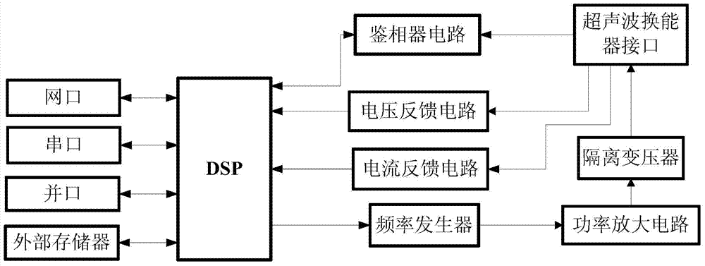
[0035] Such as figure 1 As shown, embodiments of the present invention provide a driving power supply for ultrasonic transducers, including:

[0036] a frequency generator, controlled by a control signal, for outputting a drive signal to the ultrasonic transducer;

[0037] A phase detection circuit is used to perform phase detection on the output signal of the ultrasonic transducer to obtain a phase detection result;

[0038] a digital signal processor, configured to generate the control signal, and perform phase locking according to the phase detection result;

[0039] Wherein, the control signal generated by the digital signal processor after phase locking can control the frequency generator to output a driving signal to make the ultrasonic transduce...


PUM


Abstract

The invention provides an ultrasonic transducer driving power supply comprising a frequency generator, a phase discriminating circuit and a digital signal processor. The frequency generator is controlled by a control signal and used for outputting a driving signal to an ultrasonic transducer; the phase discriminating circuit is used for generating the control signal and performing phase locking according to a phase discrimination result; according to the control signal generated after phase locking, the digital signal processor is capable of controlling the frequency generator to output the driving signal enabling the ultrasonic transducer to generate resonance. The digital signal processor controls the frequency generator to sweep frequency for the ultrasonic transducer, the phase discriminating circuit discriminates the phase of the output signal of the ultrasonic transducer in the process, then the digital signal process determines resonance frequency of the ultrasonic transducer according to the phase discrimination result and outputs the control signal via phase locking, the frequency generator can control the ultrasonic transducer to maintain operation under the resonance condition, and accordingly energy conversion efficiency of the ultrasonic transducer is improved.

Description

technical field [0001] The invention relates to the field of ultrasonic bonding, in particular to an ultrasonic transducer driving power supply. Background technique [0002] The ultrasonic bonding process refers to the high-frequency vibration of the transducer excited by the ultrasonic generator, so that the mechanical energy of the high-frequency vibration is converted into heat energy, thereby realizing two metal materials between the metal wire and the integrated circuit pad and the lead frame pin. hotbonding. The process is simple and efficient, and can complete the connection of solder joints in milliseconds, so it is widely used in the field of semiconductor chip packaging. [0003] In the above process, in addition to the quality factor of the transducer itself, the conversion efficiency of ultrasonic energy into mechanical energy through the transducer is the key technology that determines the welding quality. Ultrasonic transducers have the highest conversion ef...

Claims


Application Information

Patent Timeline
Patent Type & Authority Applications(China)
IPC IPC(8): G05B19/042
CPCG05B19/0423
Inventor 刘娜于海波谢珺耀
Owner CETC BEIJING ELECTRONICS EQUIP
Learn More