
Method for producing an LED module and LED module

A technology for LED modules and housings, applied in semiconductor devices, electrical components, circuits, etc., can solve problems such as enhanced strong reflection, color fluctuations, etc.

Inactive Publication Date: 2015-04-08
OSRAM GMBH
View PDF7 Cites 0 Cited by
  • Summary
  • Abstract
  • Description
  • Claims
  • Application Information

AI Technical Summary

Problems solved by technology

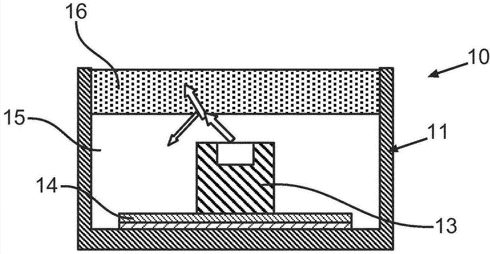
In addition, local delaminations occur due to the loading of the LED modules 10 , which nevertheless increase the effect of strong reflections and for this also cause color fluctuations along the LED modules 10

Method used


Image

  • Method for producing an LED module and LED module
  • Method for producing an LED module and LED module
  • Method for producing an LED module and LED module

Examples


Embodiment Construction

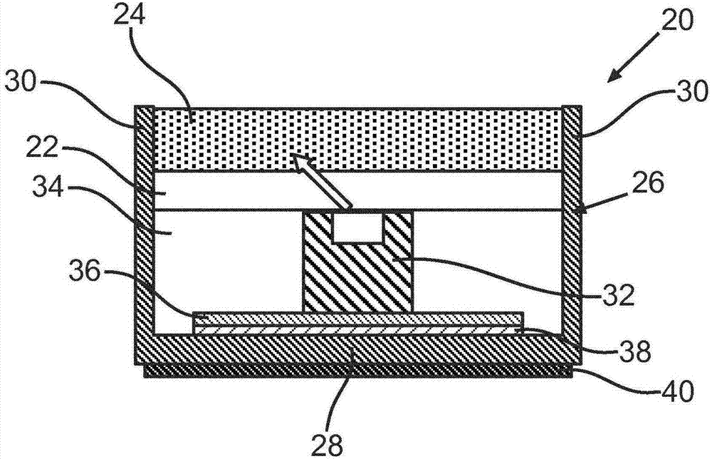
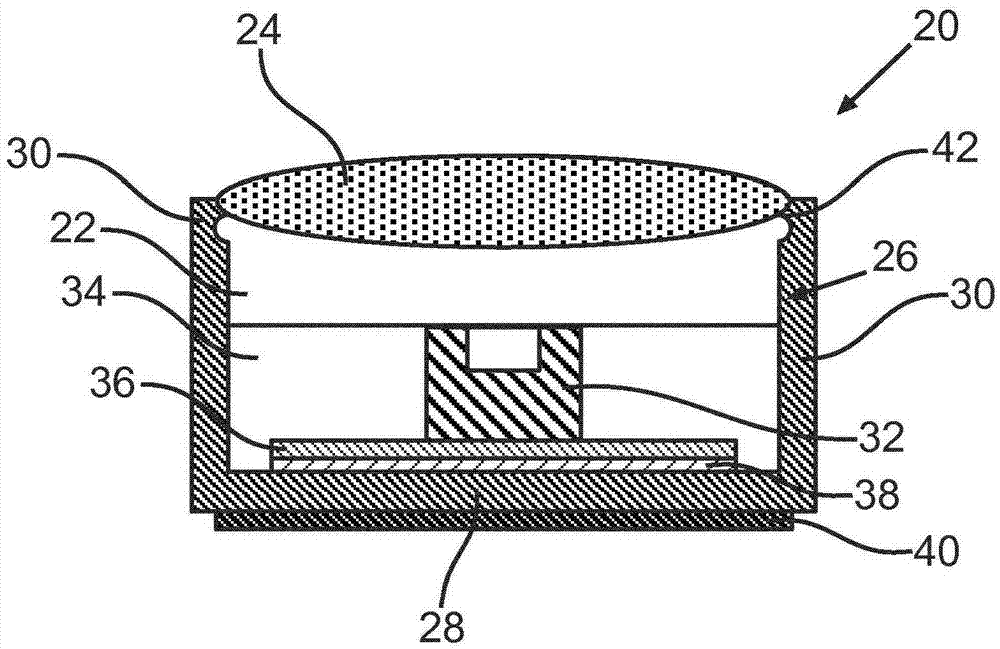
[0042] figure 2 A schematic diagram of an LED module 20 with a first base layer 22 and a scattering layer 24 of transparent design according to one embodiment of the invention is shown. The LED module 20 here comprises a housing 26 with a base side 28 and a boundary side 30 which delimits the LED module 20 to the outside. Depending on the design of the housing 26 , the boundary side 30 can include several regions, for example a front region, a rear region, and two lateral regions. The housing 26 can, for example, also be circular, rotationally symmetrical or groove-shaped. Preference is given here to an embodiment of the housing 26 which, as shown, has a U-shaped profile in cross section and extends in the direction of longitudinal extension perpendicular to the plane of the cross section shown. In the direction of longitudinal extension, a plurality of LEDs 32 are arranged linearly, in particular on a circuit board 36 which is arranged on the base side 28 of the housing 26...


PUM


Abstract

The present invention relates to a method for producing an LED module and an LED module, by means of which a high out-coupling efficiency and homogeneity of the emitted light can be provided. In the method according to a first aspect of the invention, a housing (26) is initially provided, which has a base side (28) on which a circuit board (36) with at least one LED (32) is arranged. In addition, at least one first base layer (22) made of a curable material is poured in a non-cured state into the housing (26). A scattering layer (24) made of a curable material is also poured into the housing in a non-cured state. The scattering layer (24) is poured onto the first base layer (22), the first base layer (22) not being cured when the scattering layer (24) is poured in, and after the scattering layer (24) is poured in, the at least one first base layer (22) and the scattering layer (24) are cured.

Description

technical field [0001] The invention relates to a method for producing an LED module according to the preamble of claim 1 and an LED module according to the preamble of claim 9 . Background technique [0002] Linear LED modules based on the prior art are known, in which the LEDs are arranged linearly in series in a housing with a light exit side. In order to no longer perceive the LED as a single light source as far as possible and to achieve the highest possible homogeneity (Homogenitaet) of the emitted light in terms of brightness and color, a light-scattering matrix material can now be introduced into the housing by Its light mixing and scattering effect enables a more uniform reflection of light. In order to achieve a satisfactory light mixing of the individual LEDs, the thickness of the base material, that is to say the distance from the light exit face of the LED to the light exit side of the LED module, is correspondingly large, in particular the greater the distance...

Claims


Application Information

Patent Timeline
IPC IPC(8): H01L33/54H01L33/56
CPCH01L33/54H01L25/0753H01L2933/005H01L33/56H01L2933/0091H01L2924/0002H01L2924/00H01L25/50H01L33/486H01L33/58H01L33/62H01L2933/0058H01L2933/0066
Inventor 马丁·赖斯西蒙·施瓦尔恩伯格
Owner OSRAM GMBH
Learn More