
Wire outlet structure of plastic packaging stator and plastic packaging motor

A plastic-encapsulated stator and stator technology, applied to the shape/style/structure of winding insulation, electrical components, electromechanical devices, etc., can solve the problems of large axial size of plastic-encapsulated motors and complicated outgoing process of plastic-encapsulated motors, so as to reduce welding process, Reduced axial size and cost savings

Active Publication Date: 2015-04-08
GUANGDONG WELLING ELECTRIC MACHINE MFG
View PDF6 Cites 11 Cited by
  • Summary
  • Abstract
  • Description
  • Claims
  • Application Information

AI Technical Summary

Problems solved by technology

[0003] The purpose of the present invention is to overcome the deficiencies of the above-mentioned prior art, and provide a wire-out structure of a plastic-sealed stator and a plastic-sealed motor, which solve the technical problems of the existing plastic-sealed motor with a complex wire-out process and a large axial dimension of the plastic-sealed motor

Method used


Image

  • Wire outlet structure of plastic packaging stator and plastic packaging motor
  • Wire outlet structure of plastic packaging stator and plastic packaging motor
  • Wire outlet structure of plastic packaging stator and plastic packaging motor

Examples


Embodiment Construction

[0026] In order to make the object, technical solution and advantages of the present invention clearer, the present invention will be further described in detail below in conjunction with the accompanying drawings and embodiments. It should be understood that the specific embodiments described here are only used to explain the present invention, not to limit the present invention.

[0027] It should be noted that when an element is referred to as being “fixed” or “disposed on” another element, it may be directly on the other element or there may be an intervening element at the same time. When an element is referred to as being "connected to" another element, it can be directly connected to the other element or intervening elements may also be present.

[0028] It should also be noted that the orientation terms such as left, right, up, down, top, and bottom in this embodiment are only relative concepts or refer to the normal use state of the product, and should not be regarded...


PUM


Abstract

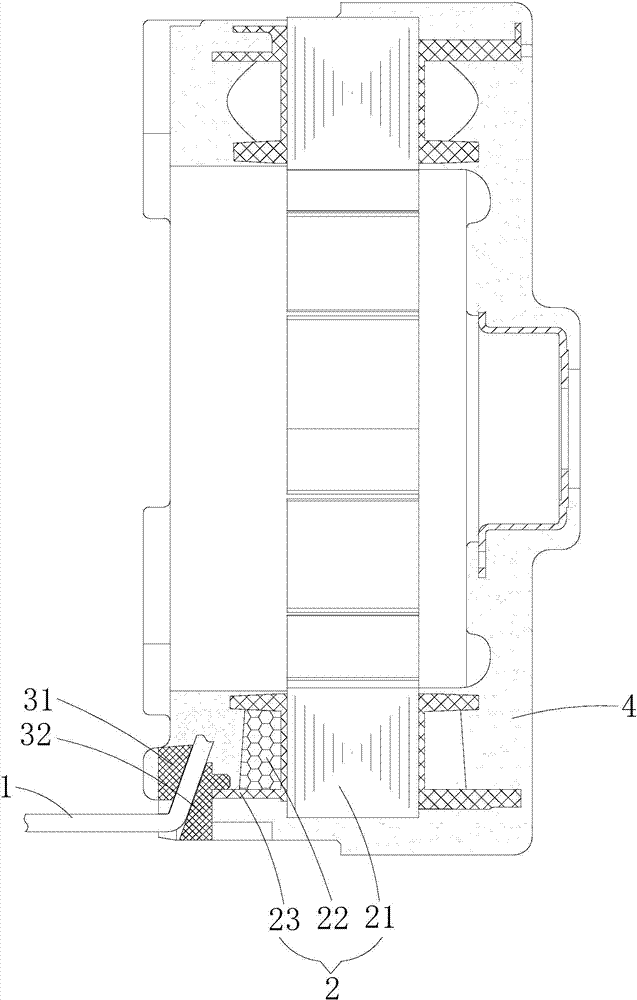
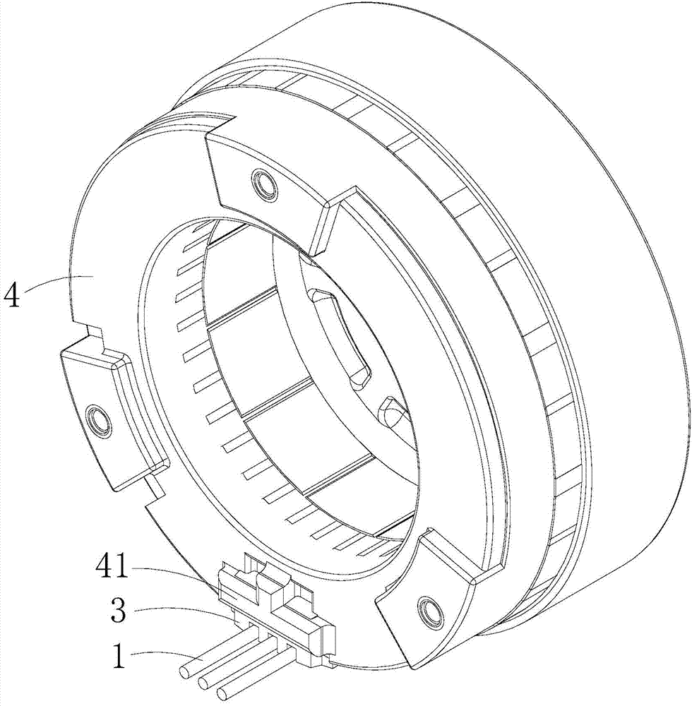
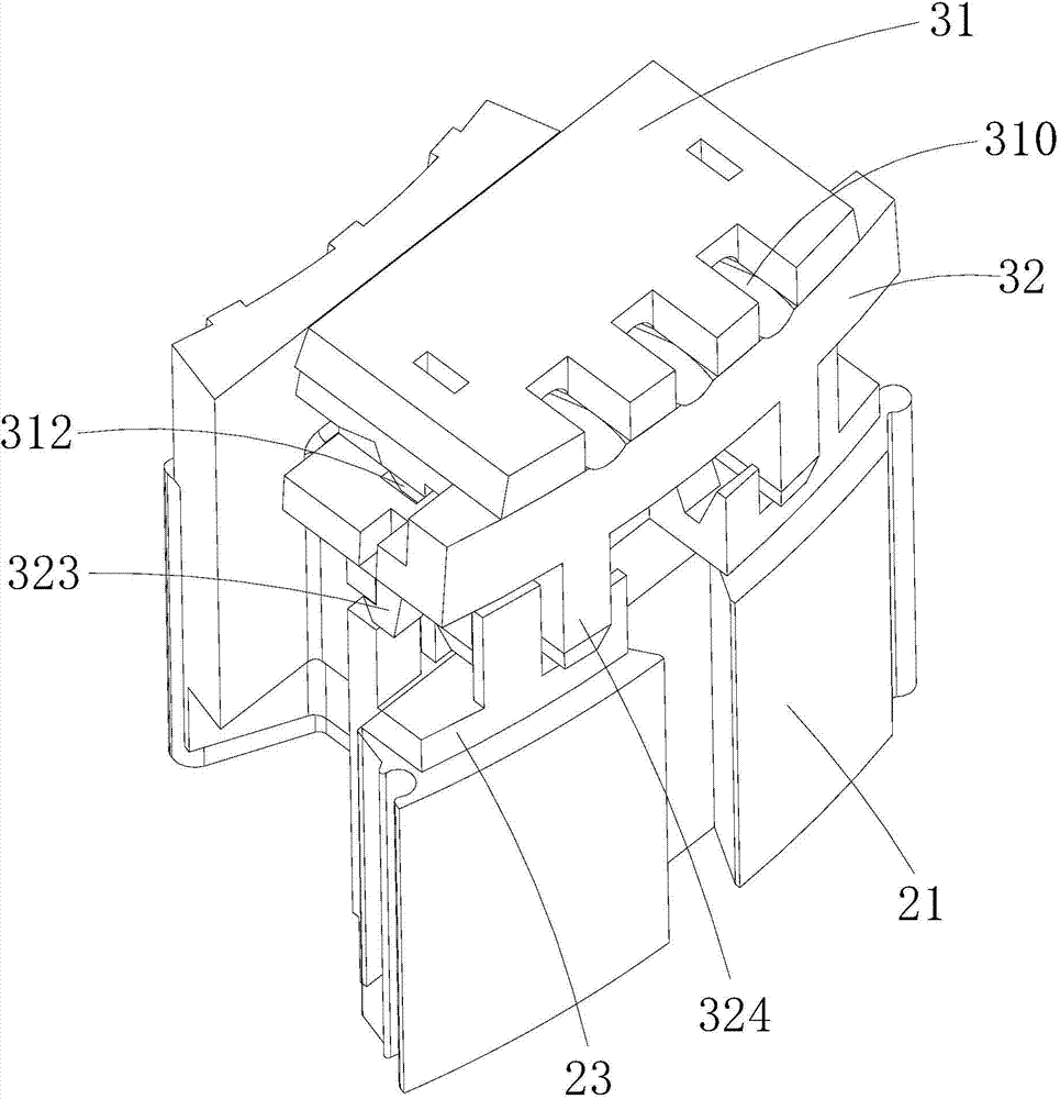
The invention is suitable for the field of motors, and discloses a wire outlet structure of a plastic packaging stator and a plastic packaging motor. The wire outlet structure of the plastic packaging stator comprises a power wire, a stator assembly, a wire clamp and a plastic packaging shell, wherein the wire clamp is arranged on the stator assembly, and the plastic packaging shell is arranged outside the stator assembly and the wire clamp in a packaging way; the stator assembly is provided with a winding leading wire; one end of the power wire is connected with the winding leading wire and is fixedly arranged in the plastic packaging shell in a packaging way, and the other end of the power wire penetrates out of the plastic packaging shell from the wire clamp. According to the wire outlet structure of the plastic packaging stator and the plastic packaging motor, disclosed by the invention, the power wire penetrates out of the wire outlet structure after being directly connected with the winding leading wire, and meanwhile, the part, which is positioned between the wire clamp and the winding leading wire, of the power wire, is fixedly packaged through the plastic packaging shell, so the fixing of the power wire is realized, the design of a circuit board is reduced, the cost is reduced, and the axial size of the plastic packaging motor is reduced; meanwhile, the welding technology between the circuit board and the power wire as well as the welding technology between the circuit board and the winding leading wire of a stator are reduced, the wire outlet technology of the power wire is further simplified, and the wire outlet structure is beneficial for increasing the production efficiency of the plastic packaging motor.

Description

technical field [0001] The invention belongs to the field of motors, and in particular relates to a wire outlet structure of a plastic-sealed stator and a plastic-sealed motor with the structure. Background technique [0002] The way of the existing plastic-encapsulated motor is as follows: firstly, the lead wires of the stator winding and the power cord are welded and fixed on the circuit board respectively, and then the power cord is passed out of the plastic-encapsulated motor from the wire clip. This outlet method has the following deficiencies in specific applications: 1) It is necessary to weld the circuit board and the power line and weld the circuit board and the stator winding lead wires, and its outlet process is more complicated, resulting in relatively high production efficiency and production cost of the plastic-encapsulated motor. 2) The axial dimension of the outlet part is too large, which leads to the axial dimension of the plastic-sealed motor being too lar...

Claims


Application Information

Patent Timeline
Patent Type & Authority Applications(China)
IPC IPC(8): H02K5/22H02K3/50
CPCH02K3/38H02K5/225
Inventor 李煜井赟甘峰李鑫期黄柒浩
Owner GUANGDONG WELLING ELECTRIC MACHINE MFG
Learn More