Charging cable high-set retractor
A technology for retracting and unwinding wires and connecting wires, which is applied in charging stations, electric vehicle charging technology, and devices for bending lead wires. The effect of increasing the service life and improving the safety factor
- Summary
- Abstract
- Description
- Claims
- Application Information
AI Technical Summary
Problems solved by technology
Method used
Image
Examples
Embodiment 1
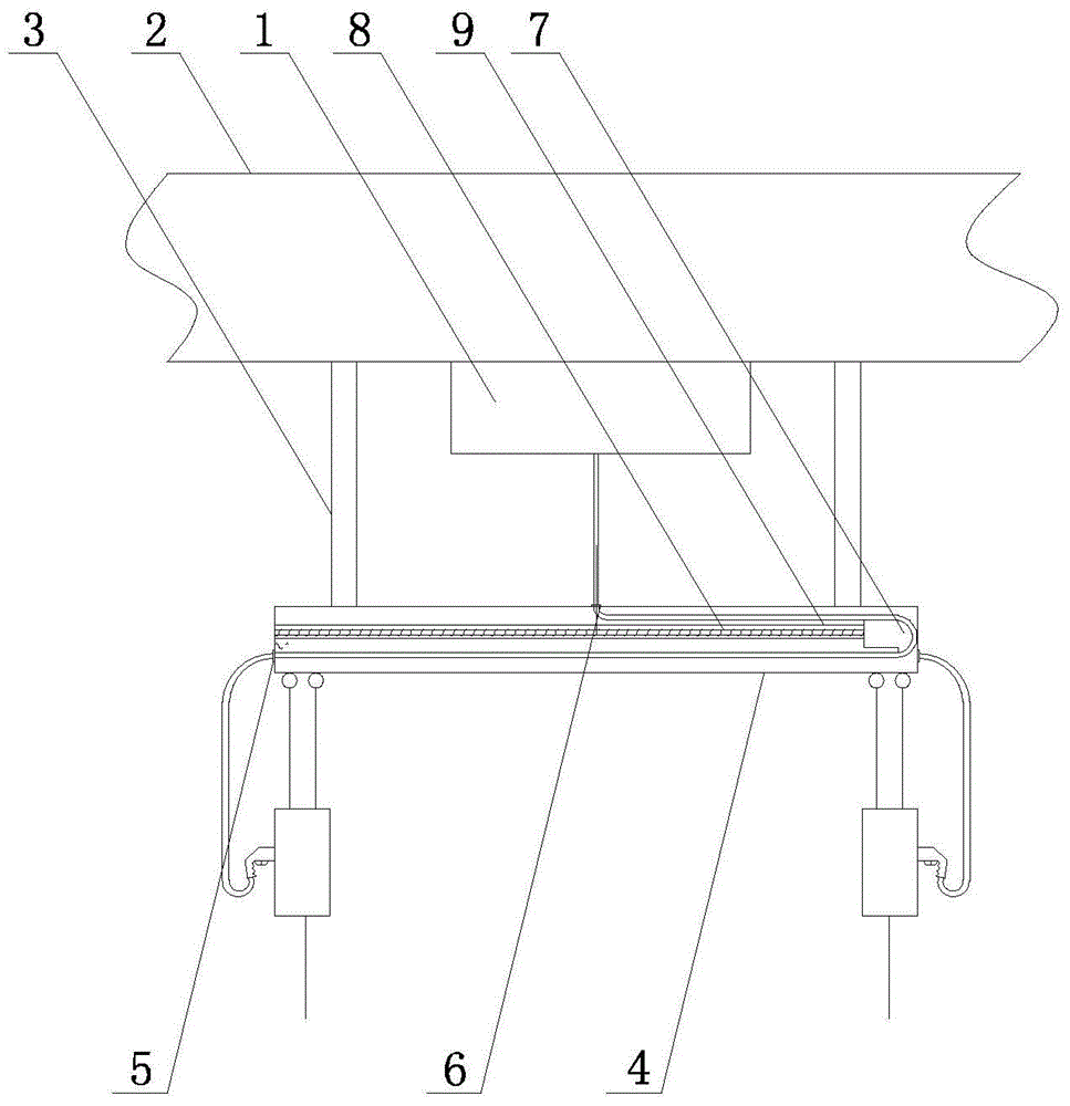
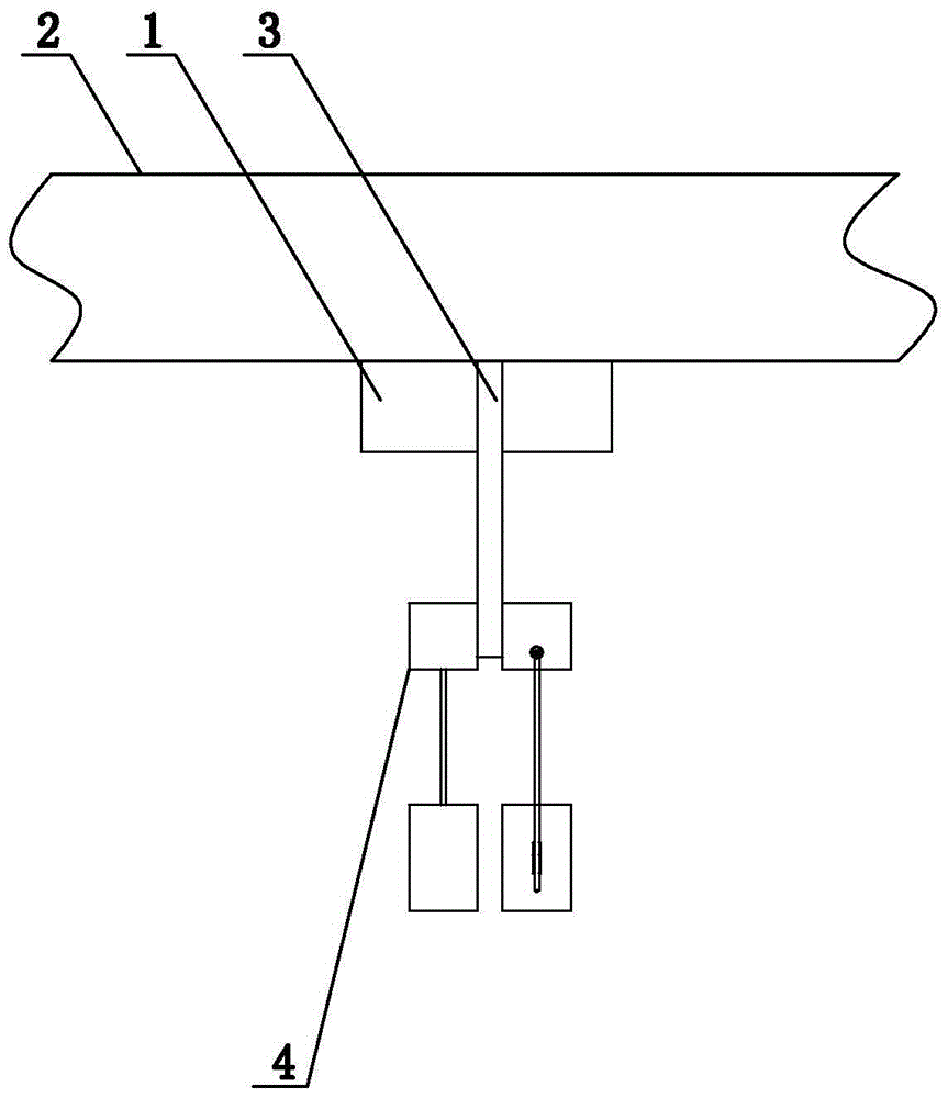
[0033] Embodiment 1: The charging connection line according to the present invention is placed at a high position, such as figure 1 and figure 2 As shown, the charging pile 1 is included, and the charging pile 1 is installed on the bottom surface of the charging station roof 2. The bottom surface of the charging station ceiling 2 is provided with a connecting rod 3, and the connecting rod 3 is located on both sides of the charging pile 1. The connecting rod 3 connects the horizontal track 4 is connected to the ceiling 2 of the charging station, one end of the horizontal track 4 is provided with an outlet 5, the position of the horizontal track 4 corresponding to the charging pile 1 is provided with an inlet 6, and the horizontal track 4 is provided with a slider 7, and the charging gun connection line is connected to the The mouth 6 penetrates, bypasses the slide block, and passes through the wire outlet 5, and a spring 8 is arranged between the slide block 7 and the end face...
Embodiment 2
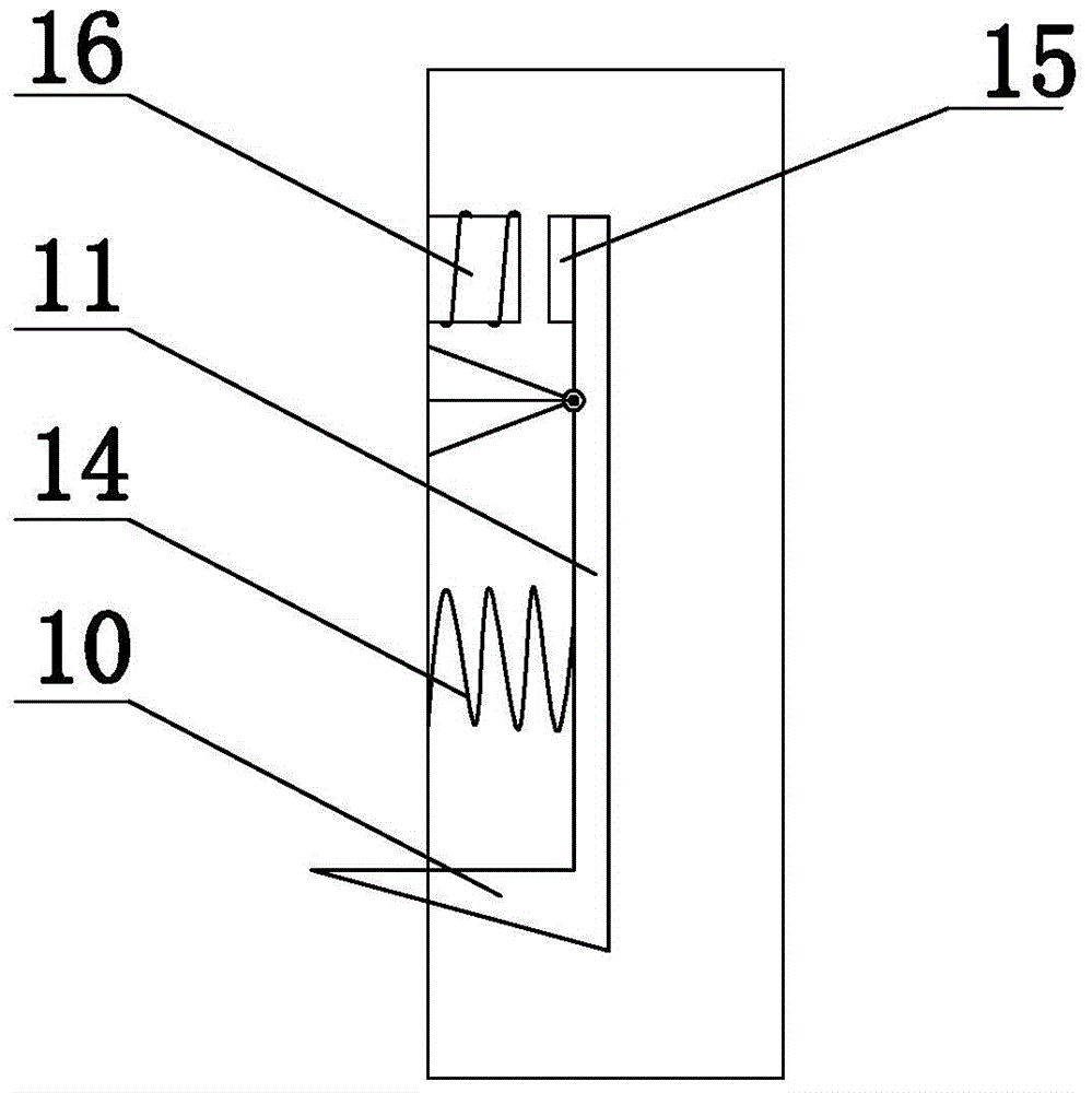
[0034] Embodiment 2: on the basis of the structure described in embodiment 1, as image 3 and Figure 4 As shown, two parallel transverse rails 4 are installed on the connecting rod 3, the outlets 5 of the two transverse rails 4 are located in opposite positions, and a spring 8 is arranged between the slider 7 and the end face of the end of the transverse rail 4 provided with the outlet. , the transverse track 4 is provided with a tooth 9, the slider 7 is provided with a locking device, the locking device is provided with a barb 10, the barb 10 cooperates with the tooth 9, the locking device is provided with a bracket 12, and the barb 10 is provided with a handle 11. The handle 11 is hinged on the bracket 12. The locking device is provided with a housing 13. A spring B14 is provided between the handle 11 and the housing 13 of the locking device. An armature 15 is provided at one end of the handle 11 of the barb 10. On the housing 13 of the locking device, a corresponding An e...
Embodiment 3
[0035] Embodiment 3: On the basis of the structure described in Embodiment 2, a chain is provided in the transverse track 4, and the two ends of the chain are connected to the two end faces of the transverse track 4, a motor is provided on the slider, and a gear is provided on the rotor of the motor , the gear is matched with the chain, a baffle B is arranged in the transverse rail 4, a travel switch C and a remote control switch B are arranged on the slider 7, the travel switch C is adapted to the position of the baffle B, and a relay C is provided in the slider 7, The power supply end of the motor is connected to the power supply through the normally closed contact of the relay C and the remote control switch B, one end of the coil of the relay C is grounded, and the other end is connected to the power supply through the travel switch C.
PUM
 Abstract
Description
Claims
Application Information
 - R&D
- Intellectual Property
- Life Sciences
- Materials
- Tech Scout
- Unparalleled Data Quality
- Higher Quality Content
- 60% Fewer Hallucinations
Browse by: Latest US Patents, China's latest patents, Technical Efficacy Thesaurus, Application Domain, Technology Topic, Popular Technical Reports.
© 2025 PatSnap. All rights reserved.Legal|Privacy policy|Modern Slavery Act Transparency Statement|Sitemap|About US| Contact US: help@patsnap.com


