
Composite solar battery photovoltaic solder strip

A technology for solar cells and photovoltaic ribbons, applied in the fields of photovoltaic power generation, circuits, electrical components, etc., can solve the problems of reduced flexibility of the ribbons, damage to the battery cells, etc., to release thermal stress and mechanical stress, reduce dosage, and improve surface adaptation. sexual effect

Inactive Publication Date: 2015-04-08
东莞市金羽丰知识产权服务有限公司
View PDF6 Cites 0 Cited by
  • Summary
  • Abstract
  • Description
  • Claims
  • Application Information

AI Technical Summary

Problems solved by technology

With the improvement of the conversion efficiency of solar panels, the current passing through the ribbon is getting larger and larger, so the conductive area of ​​the ribbon is required to increase continuously, but as the thickness of the ribbon increases, the flexibility of the ribbon is also decreasing. At the same time, the thickened ribbon will bring greater thermal stress to the cell, resulting in an increased probability of cell damage. Therefore, it is necessary to propose a solder ribbon with high flexibility and high conductive area to solve the current problems in the field of solar photovoltaic technology. question
[0003] This shows that above-mentioned existing welding strip device still has many defectives, needs to be improved

Method used


Image

  • Composite solar battery photovoltaic solder strip
  • Composite solar battery photovoltaic solder strip
  • Composite solar battery photovoltaic solder strip

Examples


Embodiment Construction

[0021] The specific implementation, structure, features and effects of the present invention will be described in detail below in conjunction with the accompanying drawings and preferred embodiments.

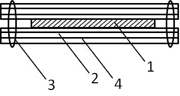
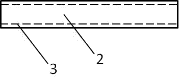
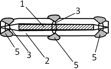
[0022] see Figure 1 to Figure 4 As shown, the composite solar cell photovoltaic welding ribbon of the present invention includes a longitudinally extending strip body, the strip body includes a conductive thread 1, a copper strip 2 and a sewing thread 3, the copper strip 2 is stitched by the sewing thread 3, and the copper foil strip surrounds the conductive Line 1. The conductive wire 1 is composed of conductive filaments arranged in parallel or twisted. The thickness of the copper strip 2 is 20 microns to 350 microns.

[0023] figure 1 and figure 2 The strip body shown in Example 1 includes a tin-coated layer 4 coated on the surface of the copper strip 2 . The cross-sectional direction of the belt body is sewn by sewing thread 3, along the axial direction of the belt bo...


PUM


Abstract

The invention relates to a composite solar battery photovoltaic solder strip. The composite solar battery photovoltaic solder strip comprises a vertically extending strip body, the strip body comprises a conductor wire, copper strips and sewing threads, the copper strips are stitched by the sewing threads, and a copper foil strip surrounds the conductor wire. The technical scheme provided by the invention has multiple advantages: first of all, the copper strips are not welded but stitched by use of the sewing threads, such that the production energy consumption can be reduced, the production process is simplified, and at the same time, equipment does not have to be improved too much; secondly, the switching of the sewing threads can enable the strip body to maintain certain flexibility and softness, and the two copper strips can perform slight movement, such that the thermal stress and the mechanical stress can be effectively released; thirdly, the number of conductor wires can be easily changed, such that the parameter flexibility of a product is enhanced, and at the same time, the conductor wire can perform slight movement inside the copper strips, such that the flexible capability of the solder strip can be improved, and the solder strip has better surface adaptability; and finally, the scheme of forming recessed grooves through the switching by use of the sewing threads and filling the recessed grooves through soldering tin can effectively reduce the amount of the soldering tin.

Description

technical field [0001] The present invention relates to a welding device for solar cells, more specifically to an invention of a composite solar cell photovoltaic welding strip. Background technique [0002] Photovoltaic ribbon is a welding device used on photovoltaic modules, which mainly plays the role of connecting and conducting electricity. The key technical parameters of the ribbon device include weldability, tensile strength, elongation, and resistivity. The currently commonly used soldering strip device is prepared by hot-coating tin on the surface of a copper strip with high elongation, high tensile strength, and high conductivity. With the improvement of the conversion efficiency of solar panels, the current passing through the ribbon is getting larger and larger, so the conductive area of ​​the ribbon is required to increase continuously, but as the thickness of the ribbon increases, the flexibility of the ribbon is also decreasing. At the same time, the thicken...

Claims


Application Information

Patent Timeline
Patent Type & Authority Applications(China)
IPC IPC(8): H01L31/05
CPCY02E10/50H01L31/0512H01L31/02008
Inventor 任立元
Owner 东莞市金羽丰知识产权服务有限公司
Learn More