A railway inertial energy power generation device
A power generation device and energy power generation technology, which is applied in the direction of engines, machines/engines, mechanical equipment, etc., can solve the problems of inertial energy that cannot be used rationally, waste of resources, etc., achieve energy saving and full utilization, easy installation and implementation, and reasonable design Effect
- Summary
- Abstract
- Description
- Claims
- Application Information
AI Technical Summary
Problems solved by technology
Method used
Image
Examples
Embodiment 1
[0029] In today's energy shortage in the world, rational use of clean and cheap new energy has become a common demand of people. In real life, a variety of power machinery has been widely used, such as motor vehicles and power bicycles on the road, trains, railways and subways in rail transit, and airplanes in the air. These existing power machines need to consume fuel and electricity to be driven, but when they are moving or in working condition, a large amount of energy is still lost in nature because they cannot be used, resulting in huge energy waste; Taking the train as an example, the train has a relatively large inertial force, which is wasted because it cannot be effectively utilized. Therefore, the present invention designs a railway inertial energy power generation device, which utilizes the inertial force of the motor vehicle The force and the generating device body arranged on the rails generate electric energy.
[0030] The working principle of the railway inerti...
Embodiment 2
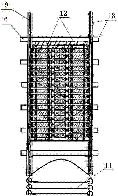
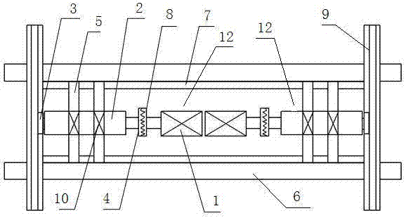
[0038]The railway inertia energy power generation device of the present invention includes multiple sets of compound power generating device bodies 12 that are arranged on the railway 13 and are matched with the railway 13, and the multiple sets of compound power generating device bodies 12 are laid radially in the two rails 9 of the railway 13 And on the crossties 6, the compound generating device body 12 is driven by the inertial force of the train 11 passing through the railway 13 to generate electricity; the multiple groups of compound generating device bodies 12 are extended and installed on the railway 13 by a plurality of compound generating device bodies 12; Said each group of compound generator body 12 includes roller 2, generator 1 and the second gear 8 installed on the drive shaft of generator 1, and also includes frame 7 installed on sleeper 6, on which frame 7 is installed The bearing frame 5 that is straight with the crossties 6, the roller 2 is mounted on the bea...
Embodiment 3
[0043] On the basis of Embodiment 2, this embodiment will further explain the above embodiment: the shaft head of the drive shaft of the generator 1 in the above-mentioned compound power generation device body 12 is fixedly sleeved with the second gear 8, and the second gear 8 The second gear 8 is meshed with the first gear 4. In this embodiment, the second gear 8 of the drive shaft of the generator 1 is meshed with the first gear 4 in a gear meshing manner, and the two gears can be adjacent external meshes. (Such as Figure 6 shown), it can be the internal engagement mode of the inner and outer sleeves (such as Figure 5 shown), it can also be that the tooth surfaces of the two gears face each other in the horizontal direction and mesh face-to-face (such as Figure 7 shown).
[0044] Such as figure 1 , figure 2 , image 3 , Figure 4 As shown, this compound generating device body 12 of the present invention can be installed in multiple groups in the rails 9 of the rail...
PUM
 Abstract
Description
Claims
Application Information
 - R&D
- Intellectual Property
- Life Sciences
- Materials
- Tech Scout
- Unparalleled Data Quality
- Higher Quality Content
- 60% Fewer Hallucinations
Browse by: Latest US Patents, China's latest patents, Technical Efficacy Thesaurus, Application Domain, Technology Topic, Popular Technical Reports.
© 2025 PatSnap. All rights reserved.Legal|Privacy policy|Modern Slavery Act Transparency Statement|Sitemap|About US| Contact US: help@patsnap.com


